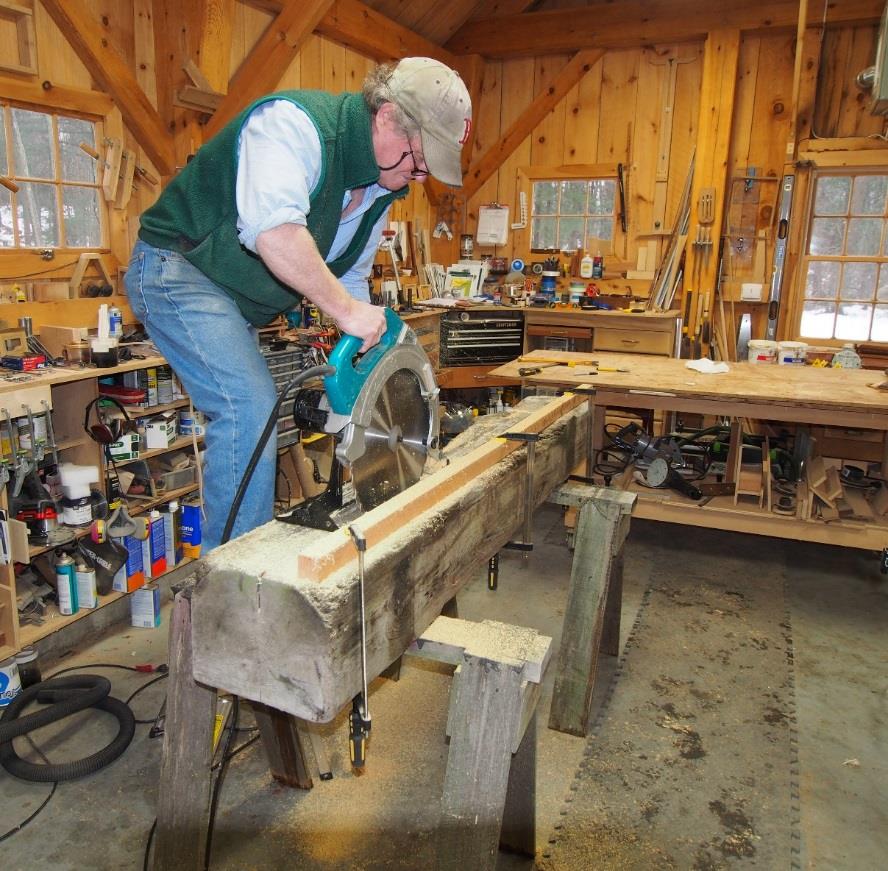
We sawed through on both sides to split the beam. Low and behold it was clearly old Long leaf (heartwood) pine that is why it was so heavy!
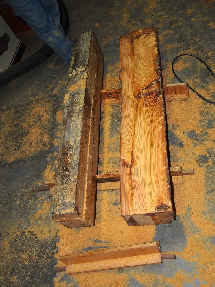
Again, because of the orientation of the large rusted pegs or nails driven through as well as other unpredictable nails it was impossible to cut reasonable 2 thick slices for a more traditional table top. I told the client that I would join these beams as they were and this would become the table top. Having sliced the beam the two pieces unfolded and presented an interesting book matched surface between the two. He agreed and so was the table top thickness and overall dimensions established.
Below was my concept design for how to build the support structure.
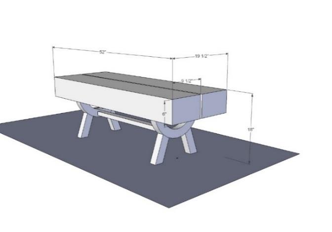
Another view of the concept design.
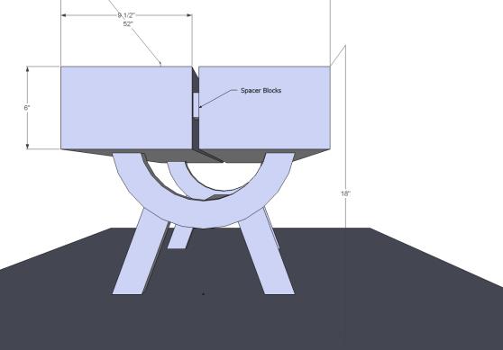
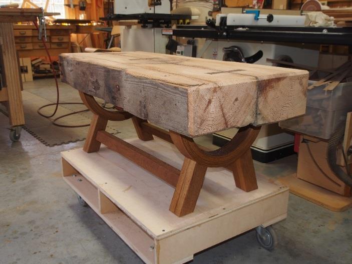
After some discussion about wood types the customer chose the base species to be in teak since that would be in keeping with other furniture in proximity. Because the beams as cut were of different thicknesses, it occurred to me that a semicircle with a U shape would allow me to vary the arc length from one side to another to balance the beams keeping the top surface flush and level.
Then things got complicated. How to create the arch of sufficient strength to support the weight. The density of this wood is high, the grain rings are 1/16- 1/8 apart, this is old growth wood (moisture content was 15%) and each beam was 6 ½ x 6 or so. Combined it was very difficult to lift with one person. Clearly the support structure would have to be very strong. If somehow the supports were to give way it would easily break someones foot or ankle!
The first step was to connect the beams, then plane a top surface. First things first. As I did this I thought I would begin to figure out the rest. I jointed the beams by drilling 3, Ύ diameter bore holes more or less equally space long the length of the beams and using a construction polyurethane adhesive, filled the holes, then pounded in three Ύ steel rods and clamped the beams together. This gave me a permanent and secure attachment of the two beams, a starting point.
As for the arch, I was worried about the stresses on the short grain at the tangent of the arch if I were to cut the arch out of solid wood (even if I could find a board of sufficient width, I reckoned that the mechanics of the forces bearing down on each of the arch legs (creating compression) would be offset by the forces of the legs on the curvature which were intuitively set at 70 degrees. Since the beams were pinned together there would not be a likelihood that they would spread and create tension which would also be offset by the legs. However, my son (Matthew), a career home builder and renovator suggested a bent lamination that would be guaranteed to withstand the forces. That motivated me into looking into a whole different approach which moved me to research the field and experiment. I love projects in which I can experiment with new techniques and learn by doing and at the same time get paid!
I knew the arch radius was going to be too great for a straightforward bent lamination of teak (inside radius was approximately 6). Bending a 1/8 piece of laminate around the form resulted in splitting the wood. A steam box was called for to make the wood more pliable. Eventually I settled on a laminate thickness of 3/32 which bent around the form without breaking after ½ hr. of steaming at 210 degrees.
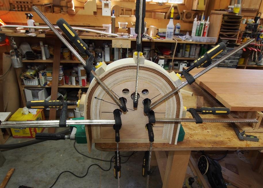
The steam bending of the plys had to be done in three stages because the spring back was huge. For each stage I added more bending ply to the form to increase the radius and each time set aside the steamed pieces to dry out at their respective radius's.
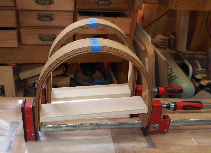
Eventually I ended up with three sets of steam bent laminations approximately 5/8 thick to give me a total final thickness of roughly 1 Ύ which I thought would be adequate and appropriate.
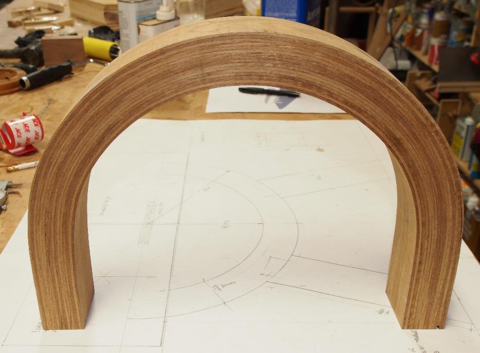
Since the spring back was so great I eventually settled on epoxying the laminates together and setting them into a female form for final assembly. The literature tended to recommend avoiding using the female form but since the radius and spring back was so acute, a female form became the right choice.
The female form worked well because it allowed me to insert laminate by laminate (with the shape of the form trapping the laminates in place) without having to fuss with clamps for each laminate. Once I had inserted all laminates into the form I could begin clamping.
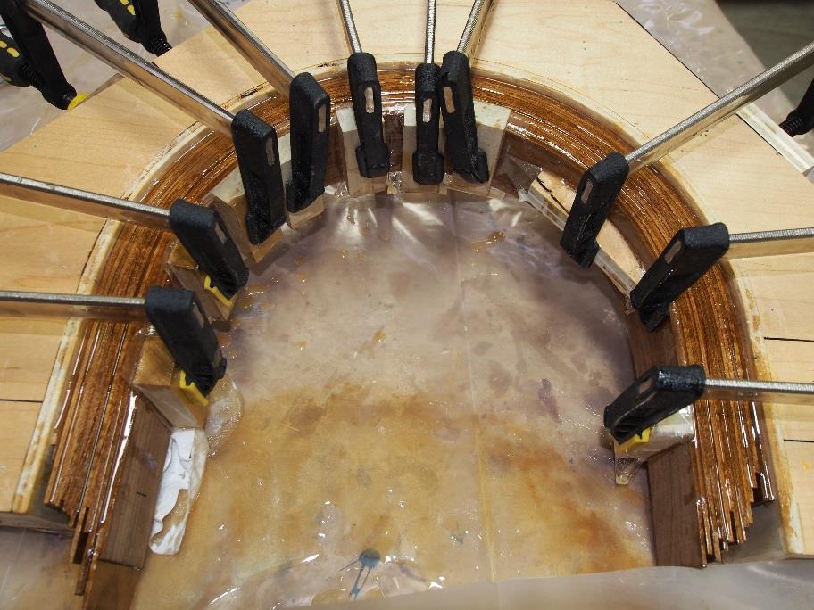
I used West system epoxy using Wests 207 activator which is the clearest and knowing that this is the ultimate all weather bond especially for these laminates with such large spring back. Once cured there was zero spring back!
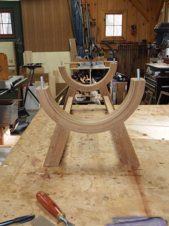
From here on it was a question of leveling, measuring and joinery (I used two loose tenons per leg to fit the legs to the curvature of the arch, each with epoxy). I also prepared 3/8 diameter aluminum dowels which were inserted 1 into the legs and 1 into the top surface, all epoxied.
To determine the cutoffs for each side of the arch I went to my full scale drawing to confirm the outside arch radius height above ground required along with the leg length to insure an overall 18 high table top surface. With this dimension in mind I set up a simple set of measuring sticks set vertically into each mortised cavity connected with a cross member attached to the vertical supports by clamps at the right height of the outside radius. With the levelled cross member connected to each upright at the desired height above the surface I transferred the assembly onto the full scale drawing and marked off the left and right cutoff marks for each side support (which were different from each other). These marks were then transferred to the arches and the cutoffs were performed on the band saw. Exact squareness of the ends was not necessary since the arch ends would eventually be sitting in a bed of epoxy and dowelled to the beams!
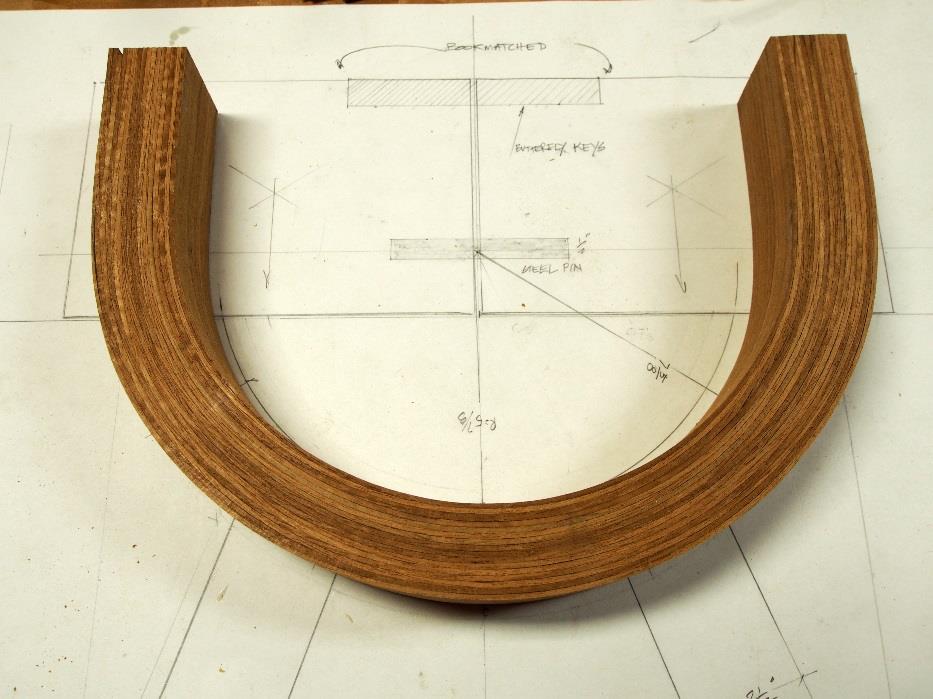
Another full scale drawing view.
Aluminum dowels.
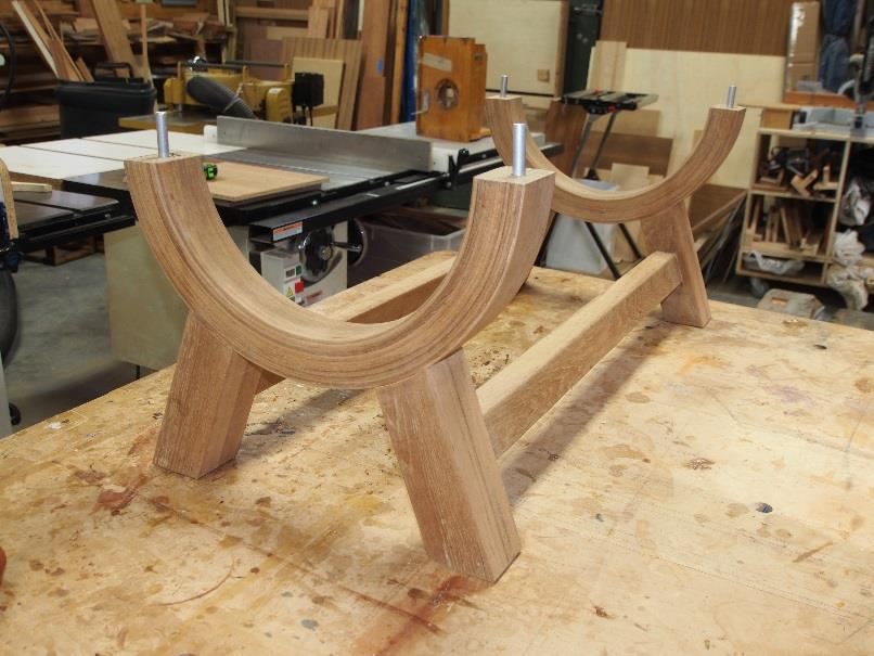
Another view of the aluminum dowels.
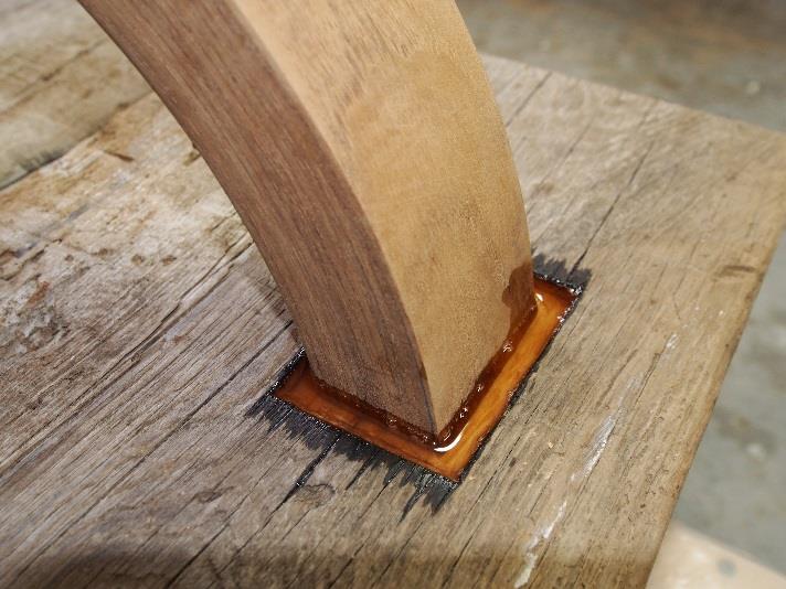
Because the two beams, side by side differed in thickness I mortised (routed) a flat surface 3/8 below the surface of the wood and about Ό wider all around the arch connection points. My idea was to create a well into which I poured West epoxy to permanently cement the legs to the uneven bottom surface of the beams and to insure an unmovable connection of the arch to the beams.
The final result...
The Ύsteel pins actually provide the strength to keep the beams in alignment and unmovable. However, to add some intrigue and additional character to the top surface I mortised in some Makassar ebony keys (1/2) thick as one would often do to bind irregular surface edges or to deter tree trunk slabs from splitting.
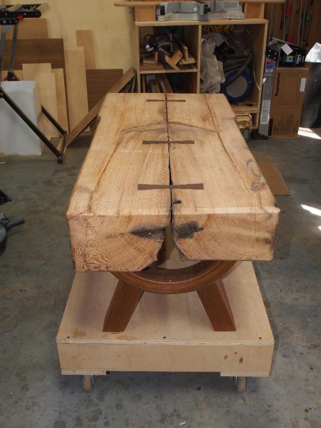
Another view of the steel pins.
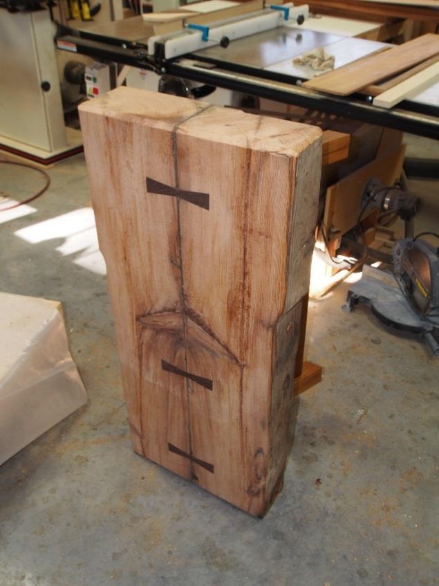
Table in its final home setting!
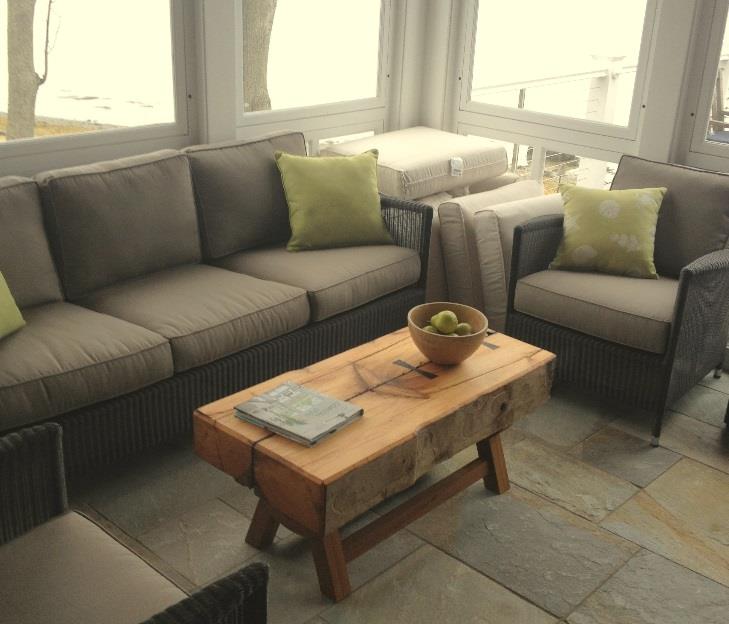
Project complete!