Question
Has anyone heard of putting a lathe or spinning indexer on their spoilboard (nemi board) and using it in synchronization with a CNC router? Applications would mainly include turnings.
Forum Responses
(CNC Forum)
From contributor C:
I think you are talking about adding a 4th axis/rotary positioner or C axis to your machine. Typically they will mount to your table, off the end, or however you choose to mount it, not to the spoilboard. Depending on your machine, you will need a driver card or another means to communicate with this new axis in conjunction with your XYZ. I have seen stand-alone controllers for Haas rotaries, but it seems scary to me to have to dual post and get them to synch at the machine. Programming is also fun; I ended up having to get pretty advanced software compared to my router. I know that some of the mid level packages claim to have 4th axis capabilities, but the first program I got that said it could, couldn't, except for very basic rotate, stop type movement. Ended up with MasterCAM X with the multi-axis module; couldn't be happier.
I don't do a lot of turnings, mostly carvings, but it is very useful for rope/twist turning. For one off's or small quantities, I still turn to the lathe with duplicator. Arguably faster as well.
There is a difference between a rotary 4th and a CNC lathe. Someone on the board may know of a high speed 4th out there, but I know I'm limited as far as how fast (rpm) I can spin. So your style of cutting changes, not so much turning as profiling along the axis, turn, repeat. I'm sure one of the guys with a large machine does things differently, but that's where I'm at.
What are these tapered clover leaves you need to make? I guess I can't picture them...
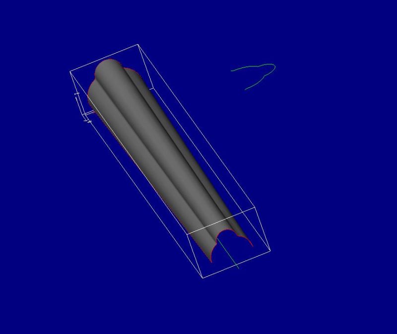
Are they solid? I suppose there could be an advantage to cutting two at a time, back to back, on the 4th, then splitting on a bandsaw. But either way, if there's internal work, I see holding them as a pain. That was my biggest boondoggle when I started on my project with the fourth; both ends had machining that I had to devise a way to fixture to in order to mount to the 4th, but not get in the way of the carving. And then of course that fixturing had to mount precisely to the 4th, so you could zero it out properly, etc., because the piece was asymmetrical, and had to reference those end/internal cuts. Moral of the story there was a .008 drift from welding heat scrapped the first fixture, and doubled the cost as the 2nd one had to be machined out of solid stock.
In my opinion, the 4th is best left to cylindrical work unless absolutely necessary. It's fun to figure out how to use it to carve asymmetrical items, but there's a lot of nonsense involved with it. Looking at your picture, it doesn't seem too bad; it's not going to matter if your C zero is off a few thou or a little backlash in the 4th exists, or if you mount the blank a little crooked. If you have a steady, consistent flow behind it to warrant the fixturing, programming and time, then go for it. But I think if you can cut them conventionally 3-axis, you are better off.
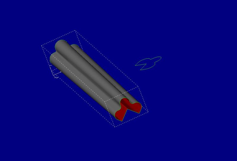
Looking at the new picture, I guess I would still be looking at trying to cut them 3 axis, on its side, then flip to do other side. It's tough to tell from the picture with it sitting in isometric, but it looks like two sides will get you all of it. Maybe not, hard to tell from picture.
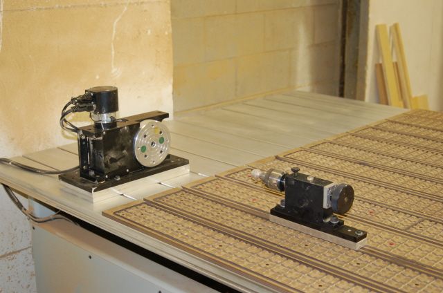
Either way, I guess it does confuse me a bit more in regard to your original question of mounting the 4th the spoilboard. If you want to cut these on the 4th, I would think you would want the axis running parallel with X or Y, but when we first started talking, it sounded like you wanted to mount the 4th in the middle of the table so that the axis was up and down, parallel to Z. I don't see how that is of any help for this part unless you have a 5 axis or aggregate head, which even then I don't know why you would use it. So I'm back to my original point of mounting the drive unit at one end of the table. I have mine set up permanently under the far end in such a way that the gantry and spindle can never hit it, and is not on the working area of the table. Then I just mount the tail stock when I need it.
Contributor R, I hear what you are saying, but I don't know if a simple programming package is going to handle what he's doing too well. It might, but the software I started with would not deal with this part well at all because it is not symmetrical around the center, not a cylinder. It sounds like you are using a machine shop rotary indexer with a stepper on it. Neat. What are you using to program? Going back to the old software issue, I had to do something similar to what it sounds like you are doing, but the program would not project to curved surface in any kind of useful manner, just got all kinds of confused.
I keep looking at your part. If you don't run those in production, how about mounting the blank between centers with an indexing plate on one end. Build several files that will machine the blank in stages. Start machining the blank based on a known angle that will cut the first back angle and first positive faces and stop there. Rotate the blank to another known angle and start cutting where you left off on the first program. Keep rotating and cutting to catch all the profile. I would do that back cut on the table saw before taking the blank to the CNC. With this process you might be able to cut two at a time and cut them apart after machining to help with production time a little.
Look at your file from the end and see if this is possible. I think you should be able to do it in 3 programs.
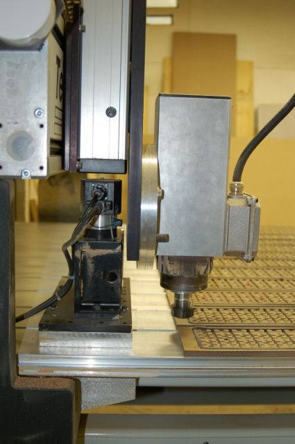
Here it is with the spindle up, but over the unit.
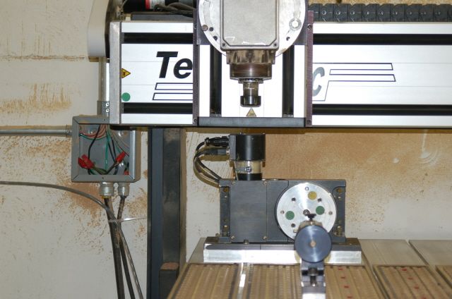
This is with the spindle down.
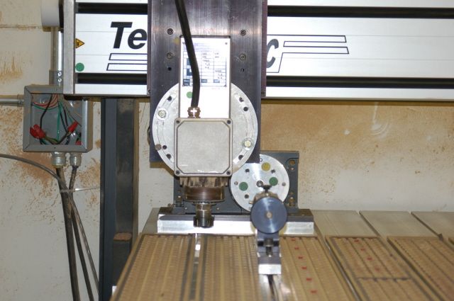
Spindle down from the side. The gantry is on its limits, except for Z, so you can see it can't be hit unless I have the fly cutter or another wide tool on. When in use, the plates that bolt to the platter with fixturing on it are long to get the work piece over the phenolic/work surface, but keeps the gantry/spindle away from the drive. Haven't had a flex issue yet, but the unit can be slid forward if necessary. The shot I didn't take would be of the underside of both the drive and tailstock, which I put dowels in that ride in the T-track groove to keep everything aligned.