Question
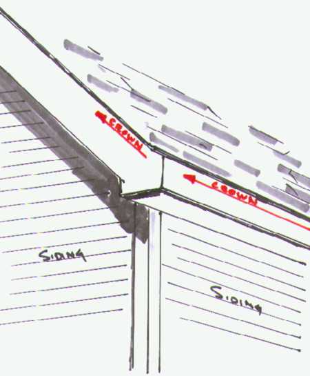
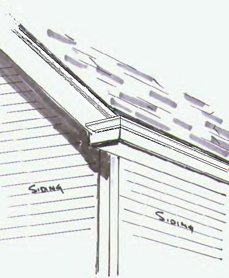
I'd like to know how to deal with sloped crown intersection. In an exterior application, this occurs when the crown that's running along the wall/soffit reaches the outside corner, and then heads up the gable side of the roof (sketch below). A similar situation can occur when installing crown in a room with a cathedral ceiling.
Can anyone explain how to handle the joint in this situation?
Forum Responses
From contributor J:
When I install crown in a room with cathedral ceilings, the moldings are at different angles to the walls. The backs of the moldings need to be planed off (or run them through the shaper and put a 60 degree bevel on both sides) because the molding at the lower part of the wall will be standing up straighter than the piece running up the angled ceiling. With a rake as steep as your drawing, that may not be acceptable--the steeper the pitch, the flatter the lower molding is against the wall.
Then I take two 2' pieces and make test cuts to find the angle, then cope or miter as usual. I've done this with a 3-piece crown as well as single crowns.
And if I had a choice, I would prefer to do some special effects or transitions, as long as we're getting stupid.
The drawing above illustrates that the facia and rake boards are of the same dimensions and the tail is cut off the rake--this is a good example of why it doesn't work. Also, it was already pointed out that the horizontal run gets flatter as the slope increases. All this makes for some bad-looking situations. I'm happy to state that I've never had to put up crown on such a slope.
I answer based on an assumption that could be incorrect. I assumed a detail similar to a flute, etc on the faces. If there is no flute et al and no plinth, a simple 45 degree on the gable end should work.
It took me several tries and I scratched my head bald!
A 4" wide piece cut on a 20 degree angle measures 4-1/4". Am I missing something?
Starting with the horizontal piece of crown, miter it on a 45 as you normally would in an “all horizontal” situation.
Take a small piece and miter it also on a 45 so it meets the first piece (for the moment, this small piece would run horizontally if it were installed right now).
Now take that small piece of crown and lay it on its BACK and cut it at 22 1/2 degrees. You’ll wind up with a triangular transition piece. The “top” of this piece will be at a point while the bottom of it will probably wind up an inch or so wide (depending on the overall size of the trim).
Nail this piece to the first one. Now the crown that will be applied to the gable can simply be mitered in at 22 1/2 degrees and it will meet the small transition piece perfectly.
The same solution applies to a cathedral ceiling except obviously for the bottom horizontal piece of crown, you would have to rip the back of the top of the trim to get it completely against the sloped ceiling.
How To Install Crown Molding on a Cathedral Ceiling
by Wayne Drake
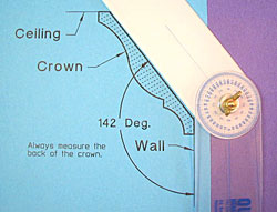
Before you make any cuts, check the crown moulding angle by doing the following:
Trace an outline of the crown molding on a piece of paper and take your True Angle Tool and measure as shown.
Take that angle measurement and subtract 90 degrees from it. (i.e. 142 - 90 = 52 deg)
This is a standard 52/38 crown. Fifty-two degrees is the crown angle to use in the Compound Miter Chart, Crown Moulding Table or the Excel Miter Cut Program for joint "A".
The complement angle is 38 degrees. (We will use the complement angle to calculate the miter and blade tilt for joints "B" & "C")
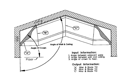
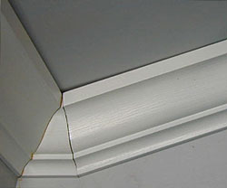
Take a close look at the above drawing. Joint "A" is a standard inside corner. The crown angle for joint "A" is 52 deg. (This is a horizontal turn of the crown molding)
Measure the angle between the adjacent walls in the corner with your True Angle Tool and, using the Compound Miter Chart, Crown Moulding Table or the Excel Program, determine the miter and blade tilt to cut the crown molding.
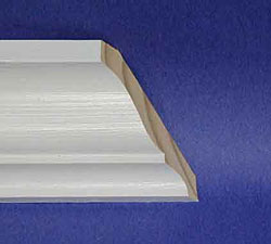
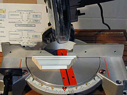
The right end of the crown is the good piece. This is the short piece that goes from joint "A" to joint "B". (I am now cutting the left-hand side of joint "B")
This is the left-hand piece that will go in the corner at joint "A".
You will always be able to see the saw cut and the pointed end will always be at the bottom of the crown molding. (Review Crown Molding page if you are having a problem here.)
Cut the mating right-hand piece that will go in the corner. This is the crown moulding that goes from joint "A" to "B".
Now this is where it gets a little tricky. Joint "B" is an outside corner. The crown turns up and continues on to joint "C".
Use your True Angle® Tool and measure the angle between the wall and the ceiling, then add 90 degrees to it to get the actual corner angle for joint "B". (i.e. Our example is a 20 degree slope roof; therefore, the angle between the wall and the ceiling is 110 degrees. The corner angle for joint "B" is 110+90=200 deg.)
The bottom of the crown is next to the fence and the top will be cut so it is 0 inches long. (Make a point)
Using 200 deg. as the corner angle and the crown angle of 38 deg. (use the complement angle of the crown for vertical turns, up or down), you can obtain the miter and blade tilt from the Compound Miter Chart, Crown Moulding Table or the Excel Program. (When you are turning the crown molding up or down, you have to use the complement angle of the crown moulding in the calculation to get the correct miter and blade tilt angles. The complement angle for the crown is 38 deg.) The Excel Program already compensates for the complement angle, therefore just input the 52 deg as asked for on the excel program page.
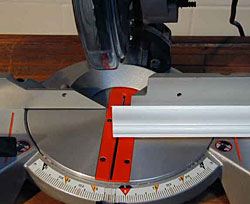
I am now cutting the right-hand piece of joint "B". Cut as shown using the above corner angle of 200 deg and crown angle of 38 deg.
Joint "C" is an inside corner vertical turn down. Use your True Angle® Tool and measure the angle that both ceilings make with each other. In our example, that corner angle is 140 deg. and the crown angle is, of course, 38 deg. (The complement angle is used for vertical turns.) From the Compound Miter Chart, Crown Moulding Table or the Excel Program, you can obtain the correct miter and blade tilt for this joint. Continue around the room until completed.
That's all there is to it! You now have the basics and can install crown molding in any room of your house that has a Cathedral Ceiling.
Reprinted with permission from www.compoundmiter.com.
Comment from contributor A:
This is not an easy fix, but I thought it might be of interest. Several old carpentry books, a few old carpenters, and old buildings I've worked on, use moldings with two different profiles in this situation. The crown along the bottom is called the cornice molding, and the crown that runs up the gable end is called the rake molding. Using an orthographic projection of the mitered cornice profile,(usually a standard crown), you can determine the profile of the rake crown. It can also be done empirically by mitering the cornice molding, then holding a piece of solid stock mitered to butt against the cornice molding and tracing its profile onto the solid stock. This has worked well for small jobs where I can shape the rake molding on common shop machines, but a large job would necessitate having custom moldings milled. One note: these two molding profiles will only work on one given roof pitch.