Question
I'm working with OpenFarmTech.org in developing a dimensional sawmill. I've got most of the design drawn up but am stuck on some parts that I need more information on.
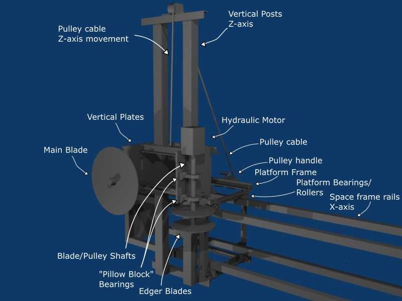
So far we've decided on a design similar to the Mobile Dimension Sawmill, with a space frame (for stability) on two "I" beams for x and y axis movements, a cage surrounding the space frame with bearings to grip it on all sides, a vertical plate or beams on the cage with another plate attached with bearings and adjusted vertically with a pulley for the z axis. The saws are mounted on the vertically moving plate and powered with hydraulic motors. We are using the hydraulic pump on the open source LifeTrac tractor to power the motors.
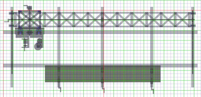
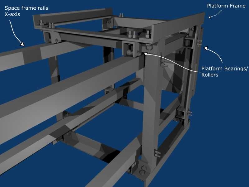
1. Will the current design of the rollers/bearings work? Will they have trouble going over sawdust that gets on the track? Are they strong enough to hold the saws and everything (250-300 pounds)? Is it going to be too hard to build the cage to get them to fit on the space frame tightly so it doesn't wobble around and make bad cuts? The bearings are flat rollers on a bolt with spacers in a kind of U-channel bolted to the cage. They have 3 bearings on each set in the picture, but we're thinking of using just 2 on each set. They roll on the flat sides of square tubes that are the edges of a space frame. All sets are the same on top, bottom, and sides.
2. How are the rollers/bearings on other sawmills with moving saws designed? I would guess that many CNC machines would also have rollers that would be similar. Are there any pictures or online patents or design details on how other rollers work? I've heard that there are some that have a V shaped bearing in a groove to work like a track. Is that what we're going to have to do? I have also seen some bearings with springs on the shafts that pull them tight against the surface they roll on.
Forum Responses
(Sawing and Drying Forum)
From contributor S:
I assume you did not show the webbing to keep the draw simpler. Your side bearings need to be attached perpendicular to the way you have them so that they can be adjusted to the frame. They won't have much load, so a rub type part would work too. Rocking error is based on the length and width of the saw base.
There are many mills that roll as you have it, assuming the rollers are on the top rails only. Other designs, which there are many examples of, do it differently. Something for you to look up.
What size saws are you planning to use and how much horsepower on the hydraulic motors?
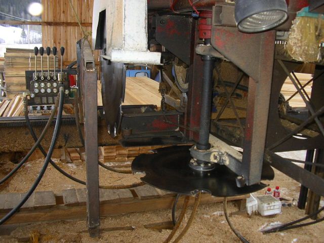
My mill runs back and forth on a couple of 1 5/8 cam follower bearings. I bought my mill used, replaced all the bearings when I set up, and have over 1000 hours without any sign of wear. Another bonus with the cam followers is they are used in all kinds of farm equipment, so they are cheap and readily available anywhere there are farms.
I have 4 cam followers on the left side of the carriage that run on a piece of flat bar. The right side of the carriage rides on small steel wheels and has two bearings at the back of the carriage that track each side of the rail on the right. There is also a steel tab that runs under the gear rack on the right side and only makes contact if the saw tries to jump up. I mounted a piece of a broom on the front of the carriage that keeps the rails clean except on wet days when I'm sawing pitchy wood.
Just read your blog. 1/8th wall is too thin and will flex, also it will rust/wear through in 2000 to 3000 hours of use. Did you forget about 100 feet of hydraulic hose, valves, flow controls and fittings in your price list (about $1000)? Your saws are mounted too high and they are too small. You will not be able to cut anything bigger than a 3x6. Farmers want 2x8 and 2x10 for barn roofs and 1x12 for siding or wind break.
That would simplify the fabrication a lot, but I looked at the weight of the sizes of I-beams I would need and they look like they would be too heavy/expensive compared to the space frame. Maybe if the beam was small and placed on it's side with v-groove wheels running on the flanges. I need to get a CAE program running so I can test to see how light the beam can be to see if it's more cost effective, though.
Contributor S: "The answer to your question is to determine the blade position error due to the design and compare it to the error specification. I don't know what a good wobble specification would be; my guess would be 1/16"."
It seems like it will be hard to tell until it's been built. It might depend on how tightly things are held together. Maybe with the bolts the tightness can be adjusted.
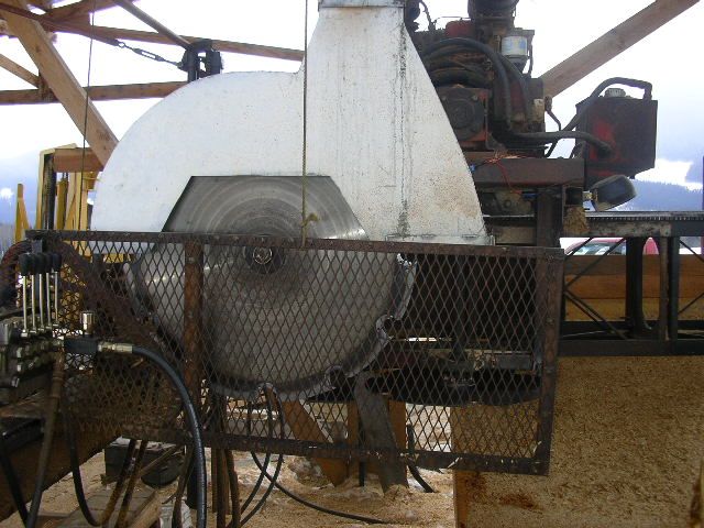
Contributor W: "I think I'd weld angle iron to the top of your box beam frame so the top would be an inverted "v". Then buy the carriage wheels from Cooks saw and machine to run on the "v"."
Yep, I'm looking into using v-groove wheels on the top with possibly a small T-beam or angle with one edge sticking up or as an inverted V.
Contributor M: Excellent advice and pictures - thank you! I couldn't find the triangular beam sawmill design from Australia, though. It would be interesting to see the unique design. I hadn't seen the Duncan sawmill yet. I can kind of see how they set up some of the hydraulic hoses from the pictures. I looked for more dimensional sawmill designs on sawmillexchange but I think I've seen all of the main designs on there.
We should actually be using a 20" main blade and a 12" edger; the 10" was an error on the BOM - thanks for spotting it! We need to saw at least 4x4s and 2x8s. It would be great to be able to supply a larger market but a larger main blade will raise the initial cost too much. I'm redesigning the saw platform right now so I'll see if I can make the main blade and edger mounts adjustable for different sized blades. Then it should be able to scale up to a larger market once an operation has gotten established. Your pictures helped a lot in showing how things are set up!
The main motor is 16 HP. I don't know the HP for the edger motor right now.
Based on the feedback I've gotten I'm going to try 4 v-groove wheels on top and secure the rest with cam followers.
Would changing the space frame rails to 2x2x1/4" angles work? How thick are the Mighty Mite's frame parts?
We didn't add the hoses, valves, flow controls, and fittings into the BOM because it's assumed that the necessary parts will be available as part of the general infrastructure. Thanks for spotting that! We should make another section with the other infrastructure costs included.
I also realized that the saws were too high a few days ago and am working on redesigning the platform so it will work correctly. Thanks to your pictures I've also moved the pillow blocks out of the way of where the lumber needs to be so the maximum size can be cut. I'll also add track wipers and a board remover.
If I remember correctly, the triangular Australian mill was called a Mustang.
As far as the goal of building this thing for $2500 goes, the saw blades and the shafting to turn them is going to cost you that much. Arbor shafts for mounting saws are precision machined parts and cost a few bucks. Check out D&L double cut�s Eco Saw; it is basically what you�re trying to build but won't have the production you are looking for.
One last thing, us sawmill guys only tell you about our good days when we tell you how fast we cut. Add in getting logs, bucking, moving the logs to the mill, removing waste, sorting lumber, stacking lumber, maintenance and marketing and the mill barely runs half the day.
1. The hydraulics on the tractor will not pull the load you are trying to put on it.
2. The cost is going to be way out of what you are guessing at.
3. The lumber that you produce will be of low quality and quantity.
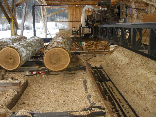
Most of the logs that people have access to are small. It takes some good equipment to move even logs 16 inch dib. Most homes and barns need lumber up to 16 ft in length at least. There is more to sawing than just running a blade through wood. There are lots of cheap small sawmills like the LT15 and the Norwood Lumberlite 24 as well as Mr. Sawmills. Band mills are safer, easier to set up and run and are cheaper to operate. They can be moved to the log site. Swing mills are good for this reason on large logs.
You should go back to the drawing board and if you wish to make a mill, look at a simple circle mill that can run off the PTO of the tractor and have a 42 inch blade with a simple track and a manual ratchet carriage. A Frick 00 is a great model and built a lot of the country.
This is coming from a guy who knows the cost of steel, studied civil engineering in college and has sawn millions of bdft of lumber on many types of mills.