Dining Table Stability
Here's an enlightening, if confused, discussion of the forces required to tip over a table based on its mass distribution. Also, this is a cool looking table. July 16, 2012
Question
Here is a CAD rendering of a dining table in the planning stage for a customer. It is to be done in quarter-sawn white oak. The top is 54" in diameter. From outer surface of one leg to outer surface of opposite leg is 31.5". The table looks stable to me, but my research on the matter suggests that it may not be, particularly if downward pressure were to be exerted on the edge of the table halfway between two adjacent legs. Short of a full mockup, does anyone have an opinion?
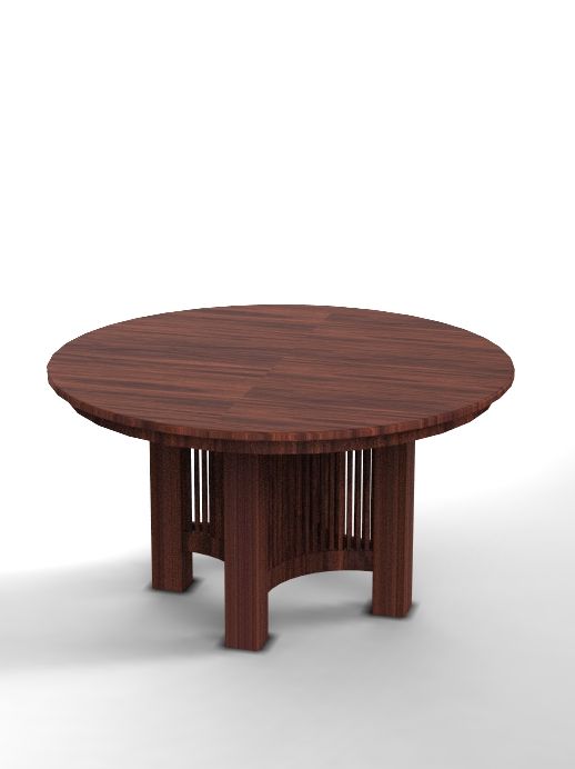
Click here for higher quality, full size image
Forum Responses
(Furniture Making Forum)
From contributor D:
I've done lots of round tables, and your table will be plenty stable with those dimensions. I wouldn't worry about it at all. I like your design.
From the original questioner:
Thanks. I appreciate your input. If it will be of any help, I am posting a 2D drawing of the dimensions of the base.
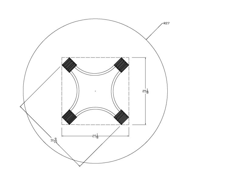
Click here for higher quality, full size image
From contributor J:
I don't think you have much to worry about. That table looks pretty heavy, and for someone to even begin to tip the table by pushing down at the edge between 2 legs, they'd have to push down with almost enough force to lift the entire table off the ground. Even then, it wouldn't instantly fall over; they'd really have to work at it to do worse than slosh some coffee or knock over a vase.
From contributor W:
The sides of the base are 22.25 inches. This leaves an overhang of about 16 inches. A good lever. I would go for a 6 leg base at the 31.5 dimension which is only an 11.25 overhang. Only 6 people will be comfortable at a 54 inch table anyway.
From contributor G:
You have L=14.5, X=39.5 and you'll have to estimate the weight for W. So, if your table weighs 100 lb, you'd need over 270 lb of force on the outside edge centered between two legs to tip it.
From the original questioner:
Thanks. 270 pounds sounds pretty good. But what about lateral or horizontal force applied to the table at its most vulnerable point - midway between two adjacent legs (say someone bumped into it or pushed a chair back using the table)?
From contributor W:
I had envisioned a lighter under structure. The CAD image didn't show earlier (for me).
From the original questioner:
How does the new information affect your previous opinion? I prefer to not go to six legs. What I did not indicate previously is that the table extends to incorporate two 12" leaves. It does so by splitting the two middle legs as shown in this rendering.
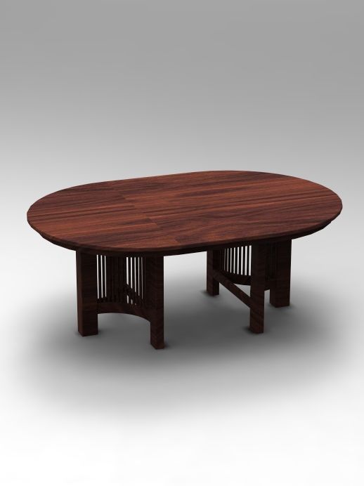
Click here for higher quality, full size image
From contributor N:
You will be fine at those dimensions. I've done many 54" tops with leaves and a base that measures around 24" from leg to leg.
From the original questioner:
Thanks. I'm feeling quite confident now and appreciate your input.
From contributor N:
Looks like you put a lot of work into the CAD drawings. Just curious if you get paid for that - do you charge a design deposit? Do those only get generated after you know they aren't just kicking tires?
From contributor D:
I'm also intrigued by your very well done CAD work. What software are you using?
From the original questioner:
The CAD is done with Alibre Design and the material rendering, lighting and scenery is done with Keyshot 2 which I obtained through Alibre, although they don't write the latter software. I have been very pleased with Alibre and found it quite easy and intuitive to learn. Their tutorials are very good. I use Alibre to conceptualize and proportion each piece so that we will have a very good idea what the completed product will look like. This is a cooperative effort that has worked for me and the people I make furniture for, but certainly is not a concept that will work for everyone. Again, thanks for your help.
From contributor Y:
Not so fast! Unfortunately contributor G misused the formula that he referenced. By using 39.5 inches for the dimension X, it suggests that the center of gravity for the table is at the extreme opposite edge of the table, which is incorrect. The center of gravity for the table is at its center, or 27" from the edge.
When a tipping force is applied at the edge of the table, the center of gravity moves slightly off center, however for our purposes it can be assumed to remain at the center. That being the case, with L=14.5" and W=100 lb and X=12.5", the maximum allowable downward force at the edge of the table will be 86 lb.
The questioner was also wondering how much horizontal force the table would resist. The answer to that question is 42 lb, assuming the table actually weighs 100 lb.
I will defer to the others who have given advice based upon their experiences, but as an engineer I wanted to correct the calculations which may result in unexpected performance of the table.
And, let me add my complements on the design. A touch of Frank Lloyd Wright. His barrel chairs would work very nicely with it.
From the original questioner:
Thanks for your comments and corrections. I suspect that the table will weigh very close to 100 pounds. Some of my earlier renderings actually looked a bit better with slightly larger bases, but legroom became a concern. I've pretty much decided to build the finished top and do some rough mockups of different sized bases to try to balance off stability, proportions and legroom comfort.
From contributor G:
The center of gravity is not where the pivot point of the lever is. 39.5" is the distance from the far edge of the table to the line between the legs opposite. Those legs will be the fulcrum over which the table will pivot. 14.5 is the lever lifting the table. The center of gravity will move toward the 14.5 side as the 39.5 side rises higher and higher in the air. Think of an off-center seesaw with a 100 lb partner 2 1/2 times further from the pivot than you. You're going to have to weigh more than 86 lb to lift him.
From contributor Y:
Unfortunately contributor G is rejecting my comments about the misuse of the formula that he referenced above. Readers should exercise caution when accepting structural advice from non-professionals, or when using formulas without fully understanding the background parameters for their use. The consequences of using incorrect information for the design of a table may not be huge, but the same misuse of that formula in the design of a beam in a building, for example, could be catastrophic.
From contributor W:
To the original questioner: Based on what you've shown I really can't see any reason why it wouldn't be stable. In fact, the concern wouldn't even cross my mind in this case. However, if I was in your shoes, here's what I would do if I still had doubts. First I'd make the top and then I'd mock up a quick base out of scrap ply. This mocked up base would simply be a structural one to emulate the footprint. Then set the top on this base and see how stable it is. The reason I suggest this is because there are times when even formulas don't work as expected. On my original prototype of a Kidney Shaped Desk I placed the outer legs in the center of the arc, because the mathematics indicated that this would be stable. It was stable, but only if no one tried to apply too much pressure on the front outer corners - which then caused the desk to tip forward. Oddly enough it took only a slight repositioning of the legs to completely change the physics, and make the desk as stable as a rock. But this could only be determined by mucking around with an actual mockup.
If you have any concerns about stability before you commit to making the actual base, then making a simple mockup of the footprint might be your best way of verifying.
From contributor A:
I'm reminded of a time when I sold building supplies. I had a customer, who happened to be an engineer, looking at carpet remnants. We had a ten minute discussion and he left without buying the 8' by 12' carpet because he insisted it wouldn't fit into his 12' by 8' room.