Question
I have researched the Knowledge Base and to my surprise found part of the answer I was looking for. I now have the math formula for figuring helical curvature, but I need to define the torsion or twist. I have researched the question under Differential Geometry but don't understand the math symbols or practical procedure. I think some of the folks who were writing about this a while back might be able to give me a hand. Weird question... I know.
Forum Responses
(Architectural Woodworking Forum)
From contributor R:
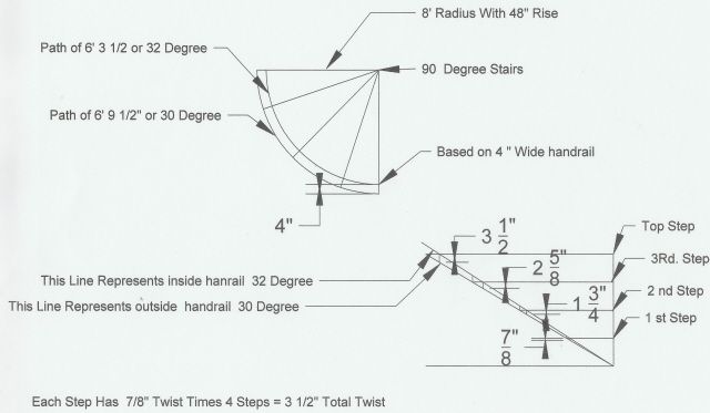
This drawing is for 8'-0" inside radius on handrail with 8' 4" on the outside of handrail. Stairs are radius at 90 degree. Path of inside arc is 6' 3 1/2" at 48" rise which is 32 pitch. Outside path is 6' 9 1/2" at 48" rise which is 30 pitch. That makes a 7/8" twist at each step times 4 steps for a total of 3 1/2" twist. The vertical lines that connect the two pitches at each step is the amount of twist per step. First step is 7/8, second is 1 3/4", and so on. And because I'm not a rocket scientist, this is the best I can do. If I'm wrong, I'd love to know the right way to figure this out. Happy brain teasers.
Make a sketch of a stair inside a right triangle. Your total rise is from first floor to the next floor. Draw the hypotenuse line from the second floor, along the outside of the treads, to the first floor. Then draw total run line that connects the other two lines you drew. The total rise and hypotenuse. Your basic right triangle, with stairs drawn inside of it. For a helical stair, you're just bending the right triangle geometry around a column. The rise and run geometry remains the same, no matter how small your column radius is.
A helix is one revolution around a column. A helical is less than one or more than one revolution around a column. To use right triangle math, you need to use a helix to start with. The two things you need to pay attention to most are the relationship between the length of the total run and the length of the hypotenuse. Take those two numbers and turn them into circle circumferences. Circumference / pi = diameter, then / 2 = radius. It's the radius calculated from the hypotenuse that you are going to use for cutting radial strips for the handrail.
If you are gluing up strips vertically for a helical handrail, what I just said does not apply. Then you are getting into twist and torsion stuff.
Contributor R, I think I understand what you're trying to explain, but I don't get your math. 8' (96") and 8'4" floor plan radii with a 48" rise in ninety degrees does not yield 30 and 32 degree pitches or path lengths of 6' 3 1/2...? Maybe you meant diameter? Either way (according to geometrical layout) the vertical measurement between the two different hypotenuse pitches doesn't seem to yield a correct total twist. Maybe I am not working it right...
Contributor P, I think you are asserting that the length of the helix = the circumference and thence the radius of the helical handrail. I wish it were that easy... The helix as it spirals up covers 360 degrees of floor plan but not 360 degrees in elevation. The ends of the helix are separated by its height (Z axis) and never come together to form a circle. The actual length of the helix covering 360 degrees is always less than a full circle. (I think I am right here).
The radius we're talking about is actually called Helix Curvature because a single plane radius will only conform to the helical curve if it is torsioned (twisted) into position. How much twist from end to end? That's the question...
I neither bend nor twist layers of wood vertically or horizontally to form handrails; I cut them from solid stock. I use 19th century geometrical layouts to do this but I dream of shortcutting this sometimes with the right math. Last month I tried a math shortcut and made some nice (and very expensive) firewood. Since I don't build bending forms or the stairs themselves, I have no way of knowing how "it fits" until I hear from the field... Oops!
Good theory is a starting point, but how much different is it from the actual handrail? Kind of like springback on glued up strips. We want to see the end result.
I was not clear on how wide the strip was in the example at Cornell, but it seemed like over compensation for the helix I drew up in cad, using their numbers.
I like to cross check the geometry and the math because I feel all warm and fuzzy when they agree. Let's do the same problem and see if we can agree (because I don't need any more firewood).
Okay, the centerline radius shall be 10". The total rise over 360 degree floor plan is 36" and the pitch is calculated at 41.98 degrees.
Cornell math yields a centerline helical curve of 13.28" which agrees with my geometric layout. The twist bevels (according to tangent geometry) is 68.5 degrees on each end and the segment of the helical curve that covers 90 degrees of floor plan is 79 degrees. 4x79 is 316 which is how I know that your helix/circumference approach was just too easy. (Sorry.)
If you feel you have a different answer I really do want to hear about it... I've been known to be wrong, especially when I know I am right.
Notes: Tangent Geometry will actually produce an elliptic pattern which is the representation of the helix on a single plane.
The Cornell math (Newton/Leibniz 1736) gives us a radius used for cutting a circular segment (annular strake) that can be twisted to conform to the helical curve.
I cut and square the stock according to the pattern and twist bevels. This is done with a band saw (careful here) and spokeshave and rasp. The shaping is completed on a special built machine.
There are a few companies now who are using 5/6 axis CNC (I know nothing about that). These are million dollar setups and if you really want to have a heart attack, ask for one part only. These guys have answers to questions I haven't even thought of yet, but they ain't telling. I've been doing this kind of work for a long time now and I have never found a simplified or easy way and that's the truth... but it has been fun.
3-axis machines on the other hand are typically large footprint machines for cutting 4x8 panels, etc. The mechanics of moving a large table (moving table) or wide gantry (moving gantry) can be more costly than the mechanics of making a spindle turn and twist in multiple directions. Do some searching and I think you'll be surprised at the cost of 5-axis machines.
This kind of approach is very labor intensive and usually reserved for high-end custom jobs, but still has some practical advantages... How do you bend a handrail around a set of winders on a 10" radius with straight flights above and below? Or how about a rail wrapping around the center pole of a spiral stair? How do you bend a large handrail with a deeply-cut and detailed profile?
As technology continues to improve, you should see more custom-type parts turning up on production jobs. This should be good news for the handrail installer who is often required to do the impossible and "just make it fit." This kind of shop-talk may help if we are willing to share some ideas and learn something new (or old).
And contributor Z, I think we may be two nuts in the same shell? I'll look forward to hearing from you. I have also figured out some math for twist.
The thing about CNC carving is it does not matter how complex the molding. If you can draw it, it can cut it. If you are only doing one piece, it may not be worth the fuss to program it. Older methods may be more practical.
Being slow myself, I had a hard time understanding why the rail had a twist at all. What helped me figure it out was to look at a circular stairway - the steps themselves. The steps or stairs are shaped just like the handrail, only at a bigger scale. For example, if a circular stairway had a well side rise of 7 inches and a run of 7 inches, the well side "pitch" would be 45 degrees or 7/7. On the "anti-well" side, that very same stairway would have the same rise of 7 inches, but could easily have a 30" run. So the pitch would be 7/30 or 13.13 degrees. If you were to draw those two pitches like I described above, you would see that the stairway is itself twisted.
Contributpr P, you're right about the elliptic helix and other helical forms. Out of the last ten pieces I've completed, none were uniform helical components.
Contributor Z, I think your description of the roll-out length of the inside and outside of the rail and the measurement between the two looks like the same approach that contributor R brought up and drew out. I couldn't seem to make that work. Maybe you could come up with some example with figures?
I am also wondering about the practicality of CNC technology for this kind of work. I don't want to be no "John Henry vs. the steam drill," but out of the last ten parts I have produced, no two were the same. Some of the profiles were large and detailed. A side profile 4 1/2" tall (I suppose) would require multiple cutters on CNC as well as cutters for shaping the top. So... multiple tool changer and programming for all cutting paths? (x one?)
I could never walk off and sip coffee because I'd be too busy biting my nails. (I wouldn't be risking any fingers, however, and that might be the best reason for going CNC.) I do know of one company producing helical handrail on CNC, but their profiles are usually small and simple. I am sure they love it and wouldn't do it any other way.