Question
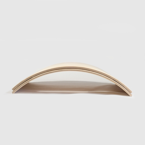
I have a situation whereby I need to do volumes of a simple chair back. See the image below. I am unable to use the vacuum feature (because of the curve in the material). I wanted to know of any alternate suggestions for holding the board in place. The material used is 8mm chipboard. Has anyone had a similar job or experience? How were you able to resolve this issue?
Forum Responses
(CNC Forum)
From contributor A:
You could easily make a fixture that will match the arc and supply vacuum with a hose or directly from the table. You have to make sure your machine will have enough stroke in Z-axis to rout the shape. A three axis router will not make a perpendicular edge on the ends. If you need the edge perpendicular around the profile you will need to use a 4 or 5-axis machine.
Laminate the two faces that make up the top and bottom of the buck so you don't leak air and screw the buck to the dedicated melamine deck board from the back. Then route holes through the buck matching the ones in the table, a gasket groove slightly smaller than the buck for the curved piece to sit on and some vacuum channels on the face of it. This will suck the part onto the buck when the vacuum is turned on.
Be careful with height. Any angles you need can be had either with dedicated tooling that has an angle built into it, or milling the edges with a lollipop cutter, (though this will take more time). It might be easier to do the edges by hand later. Once you get it working well for one part, you could build maybe three or seven more and put one or two in each vacuum zone.
I'd be looking at a curved base but use clamps. Clamp the back edge while cutting the front, and a second station next to it that holds it for milling the bottom edge. If you'd like, I can send you a slideshow file that shows a similar fixture I built for cutting cabinet door stiles and rails.
Think of it as a shaped pod with gaskets on both sides. It is a little trouble to make, but not too bad, and if you are doing lots of repeats of the same thing it's worth it.
Contributor R is right in that if you have a lot of inconsistency in your parts it can cause problems, but I'll bet you are making the blanks yourself, right? Even if not, whoever is using it is using a consistent process.
Clamps are a possibility here, but it's a lot of time to make two runs out of what could be one, and if the blanks are that inconsistent clamping itself may cause part movement.
I think that some form of vacuum fixture will do this for you, whether it is one as I describe, or some other similar application.
I've worked with way too many laminated parts to rely on them all being exactly alike. Yes, you can use thicker gaskets to keep leaking to a minimum, but vibration is always an issue for a clean cut, and the thicker gaskets tend to allow more vibration.
I owned a Multicam MG for six years. To pendulum with clamps is something I have done many times. I have also pendulumed with continuous cycle and working the vacuum valves manually.
If I had 200 parts to do I would likely keep it very simple. If I had several thousand I would be looking harder at cycle time and volume, especially if it were an ongoing contract. If your blanks are reasonably consistent a vacuum jig will work pretty well. If they are not, you make an excellent point.
In the end it is you on your shop floor looking at your material and making your judgment. You know your machine, experience level and equipment. Either way, let us know what you decide and how it works out.