A timber framer asked if I could cut a five sided ridge beam. I told him I had never cut one before but that it shouldn�t be that difficult to do, and I asked him what his specifications were for the beam. He told me that the roof was a 10/12 pitch and that the roof plane sides should be 8� wide and the rafter plane sides should be 7� with a 90� corner from these two faces. The bottom or 5th side had to be at least 3� wide. That was all he told me. Oh yeah, and it had to be 20� long with the heart/pith boxed in the center of the beam.
Looking at photo 1, you�ll see a full scale end view template made from a 1� pine board. I used my framing square with the buttons attached and a layout triangle that has degrees and roof pitch scales on it, to draw the pentagon-shaped template. After drawing the template, I bored a hole through the center of the crosshairs to be able to sight the heart/pith on the log.
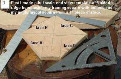
Photo 2 shows a 20� long log on the sawmill with the heart/pith leveled to the sawmill bed and red crosshair lines on the narrow end of the log.
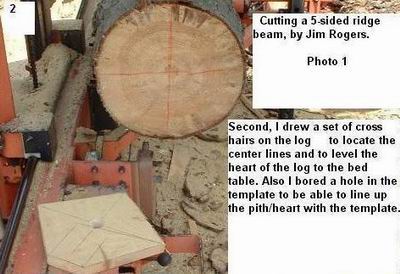
Photo 3 shows the outline of the 5 sided beam traced on from the centered template and the log rolled until one of the 7� rafter sides (labeled A) is aligned with the saw blade.
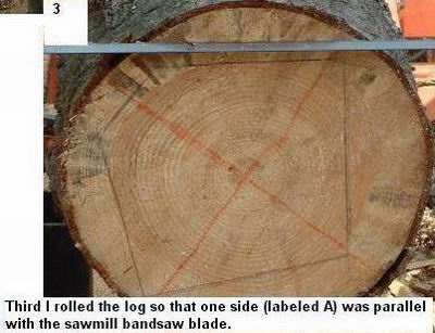
Photo 4 shows the log rolled over after side A was sawn. In this shot, side A is against the log uprights and side B is ready to be sawn.
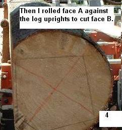
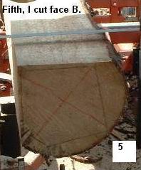
Photo 5 shows the log after side B has been sawn.
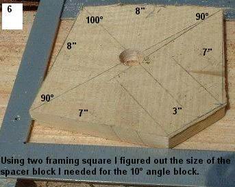
After cutting side B, I had to roll the beam over and cut side C at a 100� angle to side B. So I needed a 10� spacer block to hold up the beam to the correct angle.
Photo 6 shows how I used two framing squares to determine the size of the block I needed.
After cutting out three spacer blocks, I lifted up the beam and inserted them on the bed rails, as shown in photo 7.
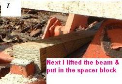
Photo 8 shows the beam with the third side (face C) cut. It was necessary to figure out where this cut should be so that face B was 8� wide.
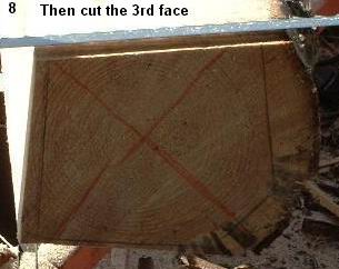
Photo 9 shows the fourth side (face D) after the log was rolled and side C was put against the log uprights. I had to again use the 10� spacer blocks to hold the beam up in the correct position as the weight of the beam kept making it slide down the log uprights. The framing square in the shot shows the 90� corner came out good.
Photo 10 shows the spacer block I made to hold the beam in the correct position to cut the 5th and final face. In order to hold the beam up on its point, the spacer block had to be a 90� x 40� x 50� right triangle. I cut three of them to use on the bed rails.
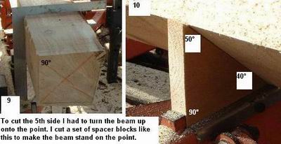
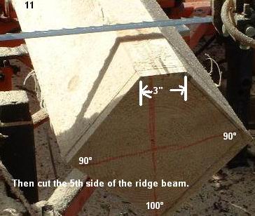
Photo 11 shows the 5th side after it was cut. Careful calculations had to be made so that each of the rafter faces came out to be 7� wide.