Hydraulics for a Bandsaw Mill
An operator posts photos and explanations for the hydraulic system in his custom-built mill. July 12, 2005
Question
We have decided to build our band mill based on one made by a neighbor. We cut up about 300 board feet recently and it worked great. Is anyone here familiar with what hydraulic pumps and motors I need to run one log clamp, mill head forward and reverse, and a log lift? I can do all the plumbing and installing, but I just need to know what gpm pump I need and what motors I need. Also, I will be running the pump off of a separate motor.
Forum Responses
(Sawing and Drying Forum)
From contributor I:
Here is a description of my hydraulics below:
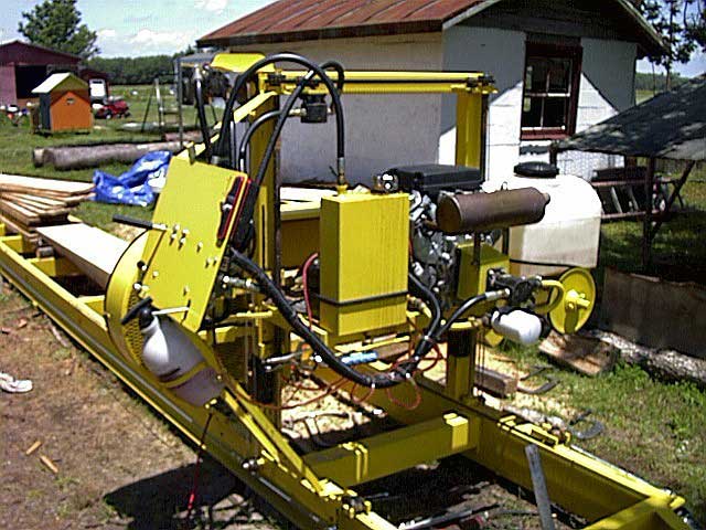
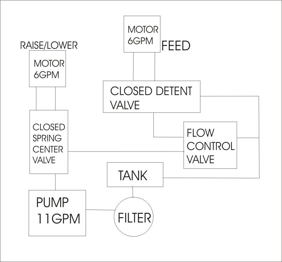
On the engine shaft is a 4" taperloc pulley, then a lovejoy connector which is linked to an 11 gpm two stage pump. The main line goes out to a closed spring center two way valve, then the working ports go to a 6 gpm motor/pump. The motor raises and lowers the head by #40 chain which is linked to two 1" acme threaded rods. The motor has a 14t sprocket, the 5 threads/inch rods has a 17t sprocket. The chain is taught with two 20t idlers. Acme rods go through 1"-5x 2" long nuts which are connected to the head platform.
The main line then goes to the 0-30 gpm flow control valve (for variable speed), then to the detent valve (both directions for forward and reverse of carriage). The working ports on the detent valve go to a 6gpm motor/pump.
The Carridge travel-hydraulic motor is linked straight to a 30:1 gear drive and the motor to the 30 side ( fast side). The 1 rev side goes to a 3/4" shaft that goes through the top square tubing over to the other side of mill. On the 3/4" shaft are two 4" grooved pulleys to grab the 7/32" cable which runs the length of the 25'x 8" channel frame. Then main line goes to hydraulic tank then back to filter. Hope this wasn�t too confusing.
Click here for full size image
From contributor I:
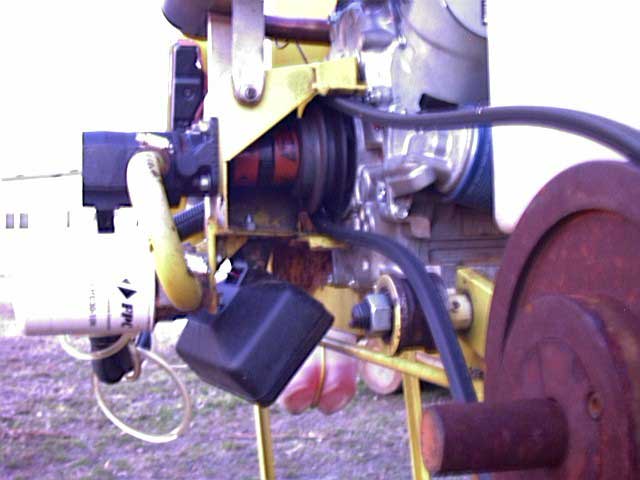
On the picture below, the engine is connected to an 11gpm hydraulic pump. It's pretty tight in there. The pump and hydraulic motors came from Northern tool.
Click here for full size image
From contributor I:
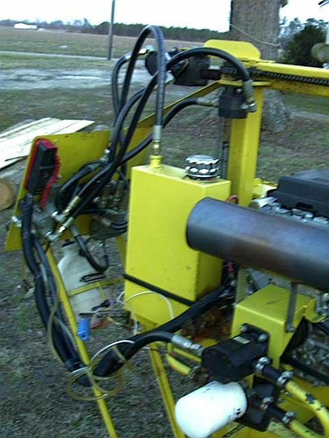
This picture shows the two hoses. They need to follow the movement of the head (up/down). The pump goes to the two-way valve and the detent valve goes to the hydraulic tank.
Click here for full size image
From contributor I:
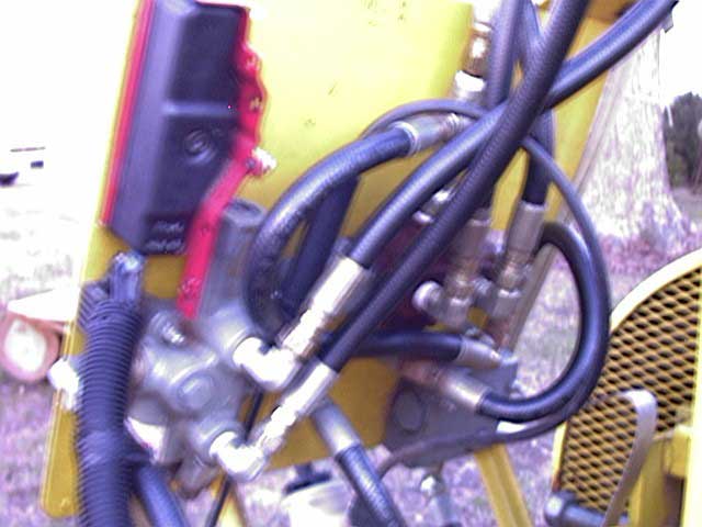
Here is a "Follow the Leader" setup:
Click here for full size image
From contributor I:
In the picture below on the bottom, the right lever is for head up/down two-way closed spring center valve. The bottom left lever is for flow control for variable speed. The above flow valve is the forward/reverse detent valve. The control panel is stationary but moves with the carriage.

Click here for full size image
From contributor I:
This is where the fluid makes the mill happen - the left hydraulic motor assembly (carriage feed). The right hydraulic motor assembly is the (head up/down).

Click here for full size image
From contributor I:
The picture below shows the link of the two threaded shafts and the feed shaft with a cable pulley. When building anything with hydraulics, it�s important to understand the pressures created. The ratios and gpm on my mill work very nicely. The mill can travel full speed in six seconds and then raise 36" in about the same time frame. I hopes this helps other people to design and build their own mills.
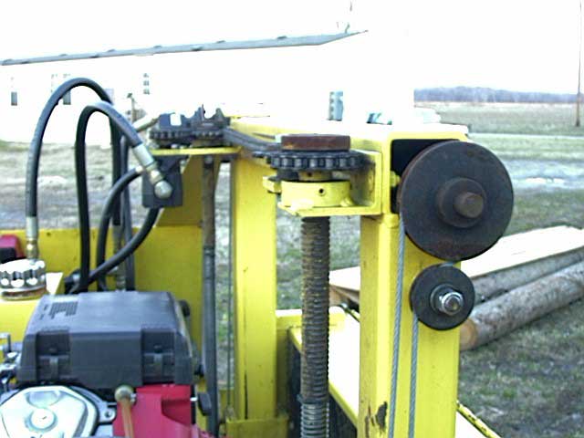
Click here for full size image
From the original questioner:
To contributor I: Thanks, that's what I was looking for. Do you run a centrifugal clutch of any kind for the blade drive?
ironworker 2/18 [ #10 -- Re: MILL HYDRAULICS ]
There is an error I have above � make sure that you do not pump 2000 PSI to the filter. The filter should be on the suction side of the pump.
Click here for full size image
From contributor I:
To the original questioner: I use a clutch to engage the drive pulley, but it is a tension lever, meaning that if you stop the blade it will kill the engine or smoke the belt.