by Charles G. Monnet, Jr.
Part One of a six part series providing in-depth information on proper sharpening and balancing procedures for jointer knives. Copies of the 167 page Knife Grinding and Woodworking Manual are available from Charles G.G. Schmidt & Co., Inc.
Balancing Knives
A. Proper Balance Very Essential.
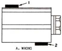
1. Types of Balance. Poor performance will be obtained regardless of the type of cutter head and knives you are running unless they are kept properly balanced at all times. The three main effects of unbalanced cutters are: 1. Sets up vibration which will give poor quality work. 2. Causes excessive and uneven pressure on the bearings which will greatly reduce their life. 3. Causes much greater noise than properly balanced cutters. There are two types of balance: static and dynamic (or running) balance. Static balance is the balance of bodies at rest. This means the balance of heads and knives when they are free to oscillate about a center (such as an arbor) under the influence of gravity alone. When a head with knives is mounted on an arbor that is placed on two parallel ways (or a similar static balancing device) and the heads and knives are of such balance that the head does not turn on the arbor, due to a heavier weight of one knife or part of the head, they are said to be in static balance. Thus, static balancing has to do with weight and its projection from the axis of rotation. In this case a projection of the knives on the head. Two cutters, mounted on a head statically balanced, could be of the same length, width, thickness, shape and weight. They could be bolted on the opposite side of the head, with the same projection, but not directly opposite each other, and they would be of static balance. (see A of figure 55).

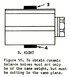
However, they would not be of dynamic balance unless they were placed exactly opposite each other and were of the same projection, weight, etc. as mentioned above. (see B of figure 55) Centrifugal force is the factor which enters the problem not found in static balance. Dynamic balancing is the equalizing of the forces set up by the cutters when revolving and in the same plane of revolution.


2. Higher Spindle Speed Requires Better Balance. The faster the cutter head speed the more essential it becomes to have good balance. It is not so much the weight which has to be balanced as the centrifugal force created by the weights (cutter head and knives) revolving at high speed. The weight of a cutter head remains constant whether it is stationary or revolving at a high speed. However, the centrifugal force tending to tear the cutter away from the head is not constant. Centrifugal force does not increase directly or in proportion with the speed of rotation but as the square of the speed. As the weight of a cutter and its distance from the center of the spindle (axis of rotation) are increased centrifugal force created by these two factors increases directly as they are increased. For example, assume a cutter weighing 8 ounces creates a centrifugal force of 40 pounds. If the weight of the cutter is increased to 1 pound the centrifugal force would be doubled (increased to 80 pounds.). The centrifugal force of a cutter 4" from the spindle will be doubled when the cutter is moved to 8" from the spindle (axis of rotation). However, when the weight and the distance remains the same and the speed is doubled centrifugal force does not double but quadruples. Thus, any increase in the cutter head speed makes balancing problems all out of proportion. Therefore, a head which might run good at 5,000 RPM may do terrible work at 6,000 to 7,000 RPM due to this factor.
Referring to A of figure 55 it can be seen that when the head is revolving each cutter is trying to fly off the head in opposite directions. Therefore, the head is being subjected to a twist similar to an airplane propeller. When the centrifugal force of the cutters in A of this figure is 850 lbs. the force being exerted upward near the inside bearings would be 850 lbs. and the force being exerted downwards near the outside bearing would be 850 lbs. This force would be acting all around the circle of the travel of the head. You can see what effect this would have on the bearings of the machine. When the head speed is 5,000 times every minute. The bearings will be subjected to a terrific eating and at best will have only a very short life.
3. Factors Necessary For Proper Balance. In order to do satisfactory multiple knife work, the heads and knives of your planing machine must be kept in very accurate balance. The uniformity must extend to width, thickness, bevels and slots, otherwise vibration will set up according to the degree of non-uniformity, and poor results will be obtained. Each knife, of a pair, should weigh exactly the same and should not vary much in shape. A wide, thin knife and a narrow, thick knife may weigh the same, but will not run smoothly because even though statically balanced they are not dynamically balanced. (both static and dynamic balance are very essential) It is not only essential that the knives should be of the same weight, but just as necessary that the corresponding ends should weigh the same. Suppose two knives of the same weight are placed in a 6" head revolving at 5000 RPM’s. Knife number one is perfectly balanced, each end weighing the same. The right end of knife number two is two ounces heavier than the right end of knife number one. Due to centrifugal force, the additional load placed on the bearings is approximately sixty-three pounds. Not only does the two ounces out of balance throw four times as much load on the bearings, but it causes the spindle to pulsate on each one half revolution thus making it almost impossible to do multiple knife work. If your knives are kept well balanced your spindle bearings will last four or five times longer. Not only do the knives have to be of equal weight, etc., but they should be set on the head with equal projection, otherwise unbalance will take place. (Be sure to read the section on Setting Knives.)
Another example of the importance of proper balance is shown as follows: On a 6½" cutting circle head, using a 2" wide milled-to-pattern bit, weighing 10 ounces, if the spindle is running at 4,000 RPM the bit will exert a pull of centrifugal force of approximately 1,000 lbs. At 5,000 RPM the pull will be about 1,550 lbs. and at 6,000 RPM approximately 2280 lbs. Centrifugal force varies not as the speed, but as the square of the speed. Thus, for proper jointing, balance is very important. Therefore, a head that is running fairly well at 4,000 RPM may show badly out of balance at 6,000 RPM. If the diameter of the heads are doubled the centrifugal force is also doubled. It is for these reasons that we recommend a 6½" cutting circle head, 4 knives, running at 5,000 RPM’s for most production operations. High frequency, as used on some moulders, is not best suited on plain surfaces or on long runs where milled-to-pattern knives can be used economically. The reason for this as explained above is because when the rotational speed of the cutter head is doubled, the effect of unbalance is four times as great and centrifugal force is increased proportionately to distort the cutter heads and knives. It is almost impossible to grind the knives with sufficient accuracy to produce accurate jointing much above 5,000 RPM. If extreme care is used in setting the knives on the knife bar for grinding, there will be very little trouble in balancing knives. We recommend use of the knife balancing way as shown in figure 57 below.

B. Measurement of Out of Balance. The "ounce inch" is generally used by engineers as the unit of measurement of unbalance. This is the unbalance effect produced by a weight of one ounce at a distance of one inch from the axis of the rotation head. By use of the following formula the effect of unbalance can be determined.
Centrifugal Force = 0.000341 W.R.N.2 lb.
When 0.000341 is a constanent.
W = Weight of difference in pounds.
R = Radius of cutting circle of head in feet.
N = R.P.M. of the cutter head.
A cutter head of 6½" cutting circle, running at 5,000 RPM having one knife weighing one ounce more than the other, even though of identical setting and in similar planes, will exert a force of 144 lbs. of unbalance. The formula for this is:
Centrifugal force =
.00034 x 3.25 x 5,000 x 5,000
----------------------------------
12 x 16
Since we want to express the force in pounds we divide by 12 to get the radius into feet and by 16 ounces get the ounce into pounds.
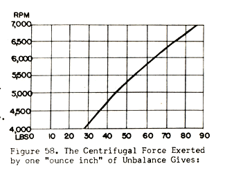
The graph shown figure 58 on page 61 was made by use of the formula given above. This clearly shows the force of the "ounce inch" as the head speed increases. As previously pointed out a amount of unbalance at a slow speed will go unnoticed, the same unbalance at an increased speed will cause serious trouble. Figure 59 on page 61 shows the great force a small amount of unbalance of knives will exert and it shows how this force is greatly increased as the spindle speed increases because centrifugal force increases as the square of the velocity (speed) the cutter head.
The same formula above can be to show the centrifugal force exerted by the knives when the weight of the knives is known. In this example assume that the knives are perfectly balanced and therefore the centrifugal force ofone knife is counterbalanced by the centrifugal force of the other. When each knife weighs 6 the head is 6½ cutting circle, the speed of the head is 5,000 RPM, then the
Centrifugal force=
.000341 x 6 x x 5,000 x 5,000
----------------------------------
12 x 16
which means that there is a centrifugal 863 lbs. by one knife and counter-balanced by the other. The figure of 863 lbs. is the amount of force which is trying to tear each knife away from the head.
Now assume a case where theknives were not set accurately and knife projects 1/8" further than the other. The formula now becomes:
Centrifugal force =
.00034 x 6 x 3.375 x 5,000 x 5,000
--------------------------------------
12 x 16
Due to the difference in projection of the one knife an unbalance of 33 lbs. is exerted by that knife. This is obtained by subtracting 896, the centrifugal force of the latter example, from 863 lbs, the centrifugal force above where the cutters were of equal balance. This verifies the fact stated in A above that even identical weights do not assure balance but the knives must be of equal projection, shape,

| Cutter Head RPM | Centrifugal Force |
| 4,000 | 28 lb. |
| 4,500 | 36 lb. |
| 5,000 | 44 lb. |
| 5,500 | 54 lb. |
| 6,000 | 68 lb. |
| 6,500 | 75 lb. |
| 7,000 | 86 lb. |
| Cutter Head RPM | Unbalance Force |
| 4,000 | 92 lb. |
| 4,500 | 117 lb. |
| 5,000 | 144 lb. |
| 5,500 | 174 lb. |
| 6,000 | 207 lb. |
| 6,500 | 220 lb. |
| 7,000 | 282 lb. |
Figure 59. Shows effect of one ounce of out of balance of knives on 6 1/2 cutting circle head at various speeds.
Editor's note: copies of the 167 page Knife Grinding and Woodworking Manual are available from Charles G.G. Schmidt & Co., Inc. you can click on their link to reach their web site, and send an e-mail request for more information, or call them at 201-391-5300.
The entire series will be available at woodweb's archive section.
Editor's Note: A good source for replacement knives for planers and jointers is American National Knife.