Question
I've been attempting to teach myself tangent handrailing. Level to rake fitting have been successful, inclined to inclined has completely evaded me. DiCristina's book, while it’s called “A Simplified Guide”, the drawings make no sense to me. The closest thing I've found is a chapter in Mowat's book called “Elementary Principles of the Cylindric System.” It shows a handrail over a 1/4 circle. Above the plan view is the elliptical drawing. My understanding is that the shaded portion up to O1 is the rise, the line from O1 to M1 is the major axis. How is that length determined, and what is the minor axis?
Forum Responses
(Architectural Woodworking Forum)
From contributor J:
The line you're referring to is the minor axis (or one half of the minor axis). It is always the level line or "ordinate". It is projected from the plan into the elevation and is then used to draw the major axis (which is always drawn 90 degrees to it).
W&A Mowat brothers were English academy science masters, cir.1900 (and not woodworkers). Their stuff is typically harder to understand than your Di Christina book. I suggest you go back to it and start with "The Cardboard Model" (plate 31). Copy it or draw it out on poster board and cut and fold it per instructions.
The lines with the big O (both in plan and elevation) are the ordinate lines (or one half of the minor axis to the curve). The ordinate is always a level line and your reference indicator. It's length in the plan projection and tangent drawing (as well as any lines drawn parallel to it) will always be the same as they are in the plan view. I know I've lost you already but until you do at least one cut-out you will be thrashing about. As you progress, I suggest a separate cut-out for all the various tangent plans. (Di Christina himself made wood block models).
If you prefer the Mowat book than I suggest you skip forward to chapter 14 and work with Fig. 223-5. Don't try to understand it all but just go through it bit by bit and re-draw it all half scale. After that you can use your face-mold template and begin practicing with some soft wood. All this stuff use to be part of a regular woodworkers' apprenticeship but is now considered obsolete. It still works though and can be fun.

If you're confused just keep going - it will become clear. I suggest that you reproduce this complete set of drawings starting with the plan view. Make the center line radius equal 9.5" Include one straight 10" tread above and below the quarter circle. The quarter circle will contain two winders, making four steps total. This should help you understand how this handrail fits over the stair.
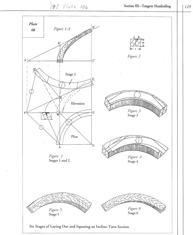
In plan view, plate 68 fig 1, imagine a riser and starting point at A and another along line BO and the last at C. Can you see then in the unfolded elevation that BE = one riser and CD = two risers?
If we were to move point E (either up or down) we would change the pitch of both tangent lines FE and ED. This is what makes it possible for a curved handrail to change its pitch from one end to the other within a single oblique plane. I'll check plate 53 in a day or two.
The two other arcs on the drawing originating from C and then D are just another way to locate G. This whole plate shows the three possible tangent plans with equal pitches along with their true tangent angles. When studying these drawings, you really have to jump back and forth from the written instructions to the drawing and identify every line and point as you go.