Question
Can anyone describe for me how raised panel wainscoting winding up a spiral stairwell is made? In other words, typical raised panel detail, but concave to apply to the wall, and slanted at the pitch of the stairs such that the rails are parallel with the slope and the stiles are plumb. Does anybody know of someone who provides these panels in paint grade?
Forum Responses
(Architectural Woodworking Forum)
From contributor A:
Do you have plans that show the details? I am sure there is more than just that going up the stairs that needs to match. Also, what is your time-frame, and location if you want it installed?
The wainscot top and bottom rails are going to be helical shaped, about 8 to 10 feet long I suppose. They need to be glued laminations, on your curved clamping jig that matches the stairwell. Your strips have to be cut at radius first, before twisting into the helical shape for glue up. Should make for an interesting setup on the shaper or router for the profile on the rails.
No useful plans exist yet at this level, but the client provided photos from a house that has a similar stairwell. I have license to redesign to make things more practical, if that's even possible. Paul is also correct that it's not quite as simple as the wainscot matching the stairs. At the landings the wainscot must transition from level to the helix, and we at least want to investigate the extra work and cost involved in having panels that would do this transition within the panel - very challenging. Thanks for your responses.
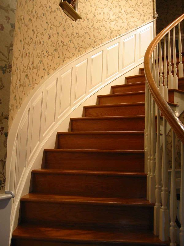
To the original questioner: I agree with your assertion that this type of wainscot project demands the highest level of fine woodworking skills. I would add that a comprehensive knowledge of stair building would also be required. A close proximity to the job site would also be ideal. As with every project, we (the client, designer and tradesperson) tend to have a preconceived image in our head of the finished product. This image is typically idealized to the nth degree, representing only the finest in materials, crafted with only the highest of woodworking skills on the best equipment. The fruition of this ideal image would test the skills of the most experienced woodworker, be quite costly and require a large time investment to realize fine and lasting results. Your work appears to attest that it can be done, but I would argue that it’s a rare occurrence for most tradespersons or shops.
I would also argue that attaining a “true point of pride for owner, maker and designer” can be realized on many different levels dependent upon the consensus formed by all parties involved at the beginning of the project. Using “ticky tack” materials and less than true manufacturing processes may be perfectly acceptable to achieve the desired effect. If the end result is a horrendous example of the craft, yet the client is satisfied, we’ve effectively completed our obligation to the project. Our obligation to the trade is personally formed. Some have none, others overflow with pride.
Limited skills, poor workmanship and lousy design abound in the end products of our industry. Examples are everywhere. These instances should be analyzed in context and compared to established norms to assess their validity as a standard practice. Most do not live up to our standards. Others however, provide innovative solutions to complex projects (radius stair work). While these different ways of doing things may fall far short of our preconceived and many times subjective standards, dismissing them as somehow not worthy stifles innovation and creativity.
To contributor B: Nope, not nearly as difficult as true radius work, but the project met the client’s budget, their expectations and lastly, we did very well. Am I crazy about the look? No, not really, but the client was satisfied when complete. Would we or have we done it the same way again? No on both counts. The photo above simply illustrates an alternative process to those presented earlier in this thread. Its applicability would depend upon many factors
First, I appreciate the segmented approach and think it definitely has its place. It's done very well. However, this particular client seems to have bottomless pockets and probably seeks a “true point of pride for owner, maker and designer” as contributor D puts it. So, flex molding and in-place lamination is out. (I can't figure out how the latter would even be possible.)
My current thinking is to follow contributor E’s advice and have cupped staves milled from custom moulder knives that I'd draw in AutoCAD. Joining the cupped staves together in a form would make a smoothly curved trapezoidal blank for a panel. My sense (pending pricing approval) is that a 5-axis CNC would be the way to go to trim the panels to size and apply the panel raise. I have a math background and a fair knowledge of Autocad so I think I might be able to interface between the site and the CNC shop. Alternatively I could run it on a shaper, but I'm thinking the CNC is the way to go to get perfect geometry, and would be even more helpful for the transition portions at the landings. My next thought is choice of panel material. I think poplar or MDF, the latter being good for stability which is critical.
Another thought - since I have some license to determine the stile/rail profile, panel raise profile, and top rail cap, perhaps I have the CNC mill the stair skirt board, base cap, bottom rail, panel, top rail, stiles, and top rail cap (chair-rail) all in the same slab - disadvantage being that seams would run continuously top to bottom and if it shows through the paint it would be a give-away that it's not built in the traditional method. Assembly and continuity at "joints" would be as good as possible however, and if it's 100% MDF there's little chance of movement in this 100 year old building. (Oh yeah, forgot to mention that it's an existing stairwell. I will be checking radius consistency very carefully.) Panels could be made with staggered joints to mitigate this telegraphing joint issue, but unless they're staggered by a pretty large dimension it might not be worth it. Plus it would seem to limit the max size of a particular panel as imposed by the CNC bed size.
In case I didn't mention this, this detail runs over the five storey height of the 10' diameter spiral staircase and is also found in two or three elliptical rooms elsewhere in the house. I think it's time for a beer.
The interiors were only concept sketches, virtually no details. I would describe them as quick sketches that were done on graph paper, photocopied 3 times, faxed once, and photocopied several more times. I love those cost/plus projects with an almost unlimited budget.
I've never been involved in a project quite as ambitious as this, but I've been following this discussion with interest. The preceding line of thought confuses me. If you were to use solid material for the panels, why would you go to the trouble of milling cupped staves to glue up the blanks? On the outside of a 10' staircase, the concavity of a 4" wide stave would only be about 1/32" deep. What's the point, if you're just prepping a blank that will be machined again after glueup? Or do I misunderstand?
We have laid up thin plies of plywood on a form and vacuumed to the radius (plus, for springback), then sized the panel, then added twisted panel raise to the top and bottom, mitering to the straight, flat verticals. Sounds intimidating, but works out well. We can make the twisted panel raise and retainer (panel) molds on the shaper in lots of pieces, jig them up for mitering, and it goes quickly. You can also do the transition from curved wall to flat, raked to level with the above.
I don't speak CNC, so can't advise you there. I do find that the old school works very well - very intuitive - especially with good communication drawings (CAD), and 21st century tools (shapers and feeders and vacuum bags) and techniques.
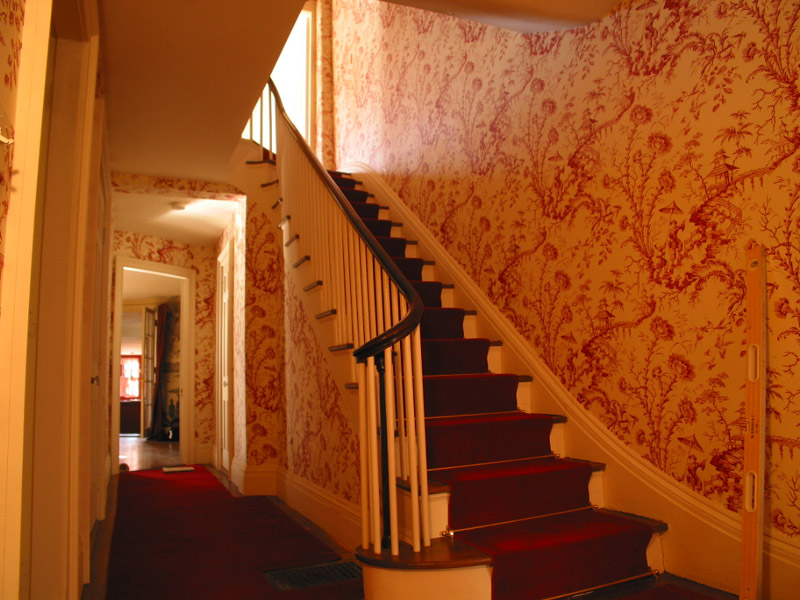
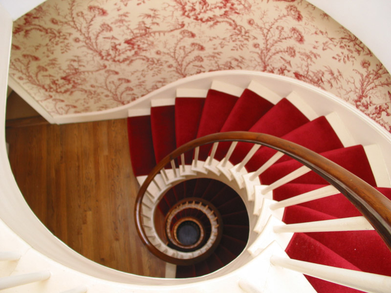
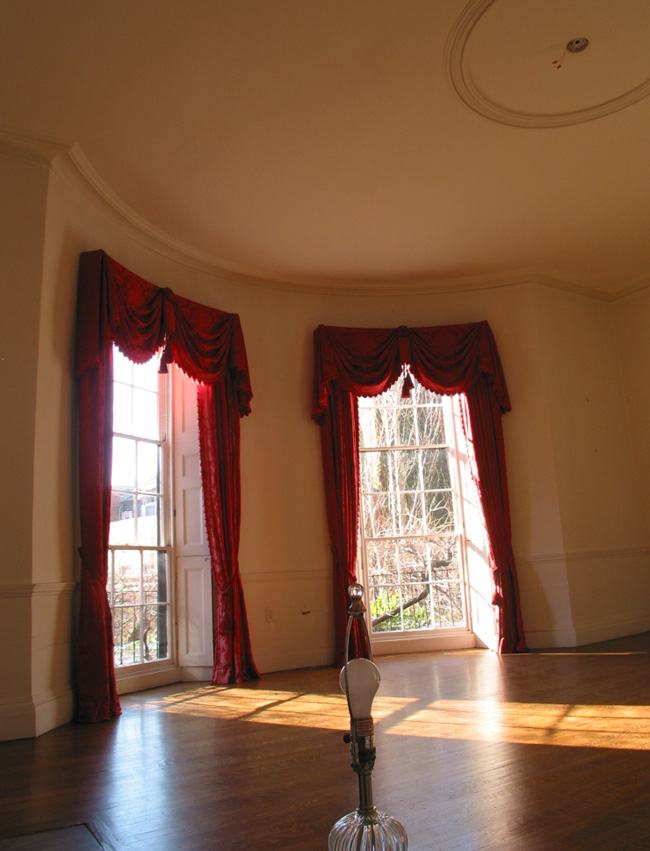
Getting back to contributor H’s question of the necessity of milling cupped staves: Last we had custom knives made it wasn't very expensive - certainly a drop in the bucket on a project of this scale. My hunch is that the benefit of getting to the point of having perfectly smooth curved panel blanks ASAP is worth this cost of the custom moulder run (unless I really underestimate the cost of the custom run).
I'm not a CNC guy either, but have talked to a few who have underscored the importance of reducing the machining time for the ball mill to hog out material to define the large-area curve of the panel field. With the custom knives, this step is already done. All the CNC has to do is cut the profile and the panel raise. Or at least this is my thinking at the moment.
To contributor F: What you describe does sound intimidating but I'm sure like most things, it's pretty easy in hindsight. I'm still concerned about using a lamination for the panels because I would be afraid of the panel raise shallow angle cut through the thin layers. I guess I'm not so worried about delamination, but telegraphing seems inevitable and that sort of telegraphing would bother me a lot more than a telegraph that reveals stave construction, which is almost quaint. But again, maybe I'm making too much of that issue and it just wouldn't be a problem. Of course I have no idea what this CNC work would cost, so if the price is sky high all of what I've written might be moot.
My next concern is the helical rails and warped stiles. It sounds like I should talk more with contributor E about the details of making the rails. If anybody has a clue about what work like this goes for in a top-tier housing market I'd love to know. My boss has approached me about taking this on and at the moment I think it would take me days just to figure my costs, and another few days of meditation and soul searching to estimate my risk/reward and opportunity cost. I'd love to hear from anyone who has done this sort of work and could suggest some ball-park figures for a fair market value.
I forgot to explain that I have a complicated relationship with the person I refer to as boss. I work for him - though indirectly, through a foreman, on a part time basis and also have my own custom cabinetry side business and am independently insured. This sort of work I would only do on a contract basis, so I do have to generate one.
Your comments have me thinking more about making the panels out of solid poplar now. Maybe 4" staves and primed with a good oil base primer on all sides. I'm guessing this is the way it would have been done 100 years ago. Cross grain movement in a 24" wide panel is something I'll lose sleep over, but the house has central AC and enormous thermal inertia, and I suppose I could consider using polyurethane construction adhesive to bond the panels to the wall surface. Does anybody know of a company or individual who has done exactly what I'm describing with panels that transition from helix to flat with varying radii of curvature?
I am wondering though - are you going to break out the plaster, and try to get your work behind the base, or do you just plan to set your work on top of the base in front of the plaster? I think I would lean toward the later. You would have to totally disassemble the whole stair to get behind the base, which is captive by the treads, which I am sure you have noticed have the balusters on their other end. It looks like a big bucket of worms to me.
Do you have the face of the frames and panels on the same plane as the base? I suppose you could make another base that goes over the existing base. If you cut off the nosing of the treads, then you only have to cut the rise/run cuts to get a decent caulkable fit.
One more thing - for the rails take a look at Ultraflex brand flexible trim. They sell an s4s stock that I have used for this type of thing. It profiles and paints really well and it will easily bend to this radius - last time I used it was on a 57" radius.
Here's another point I've been pondering in this discussion. As most everyone here knows that a hand rail or skirt board traveling up a cylinder needs to twist to remain in a vertical orientation. However, I am visualizing these raised panels and I don't see a twist.
For example, if you took a large cylinder and cut a square out of the side you would have a curved square that matched the cylinder wall. If you then angled the top edge and bottom edge to match a rise/run situation, you would still have just a curved section of the cylinder with an angled top and bottom. It seems to me that the panel situation is simplified by the fact that there is no twist in its construction. Do others agree on this point?
Judging from the number of people contributing to this thread, there seems to be plenty of people who would like to have the challenge that you are facing.
I will figure out the cross grain movement in a 24" wide poplar panel in Bruce Hoadley's book and will think more about the MDF/solid debate, and CL's idea about the 1/8" surface lamination. I too am not at all worried about stave telegraphing. As I said before, even if it happens (and I think it wouldn't happen generally), I think this is the nature of the medium, period. Embrace it!
I wonder if contributor J’s stave idea would help with the transition areas at the landings. At these points the panel simultaneously changes pitch and curvature. (I realized in talking with contributor E that the geometry of this ribbon in space is defined by only two variables: "r" - the radius of the stairwell, and, "s" - the slope at any given point along the helix. There is no twist therefore, as suggested.) Having confirmed the walls are reasonably consistent in radius, I think I can assume r to be fixed at any point away from a landing. Hopefully s is constant in the mid-flight areas too (will check). This should make a mid-flight panel from the first story interchangeable with a mid-flight panel on the 3rd, etc. The landings are very special though and while I could parameterize them by finding the r and s for incremental points along the length of the transition panel and interpolate the curve, I'm wondering if contributor J's idea for the bullnose staves might make these problem areas much, much easier. What if I use the wall itself as the form for the transition areas and glue sufficiently narrow, flat bullnose/cove staves to one another while pressed to the wall. I would wax the wall first, so I can remove and machine the panel after it's cured. The panel would be slightly faceted, but a sanding with a disc sander would smooth it out just fine at typical radii. A little bondo could be applied if not. Back for more later. Thanks to all of you. I will definitely keep you all in mind if I actually get to build this thing. I certainly can't do it alone.
So if the plaster is coplaner or very nearly coplaner with the panel surface, a helical version of a typical flat chair rail profile would bridge the gap between the ragged plaster edge and panel's top rail - a typical trim design for wainscot.
2. I don't know that the transition from curved wall to flat wall at the landings is a big issue. Panel layout can be designed so that there is a stile between a curved wall panel and the following flat wall panel. As to the transition from downward travel to horizontal travel of the rail system that is a basic change not unlike any compound curve. See the attached photo of a set of 1/2-round casings in a curved wall. This would be a similar sort of construction project.
3. The bullnose self-centering stave scheme is a good one. I used a similar idea on a small production run family gift project this past holiday season. The eight sided box was able to be glued up with nothing but a couple rubber bands due to the self-aligning joints. While working on this it occurred to me that column makers must so something similar.
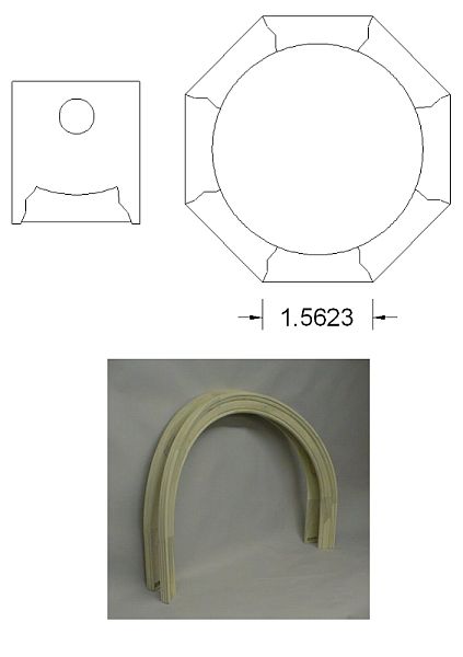
I also agree with contributor E that the panels should be laid out and divided equally from a sharply defined point where the radius begins to leave the flat plane of the landing walls. Thus there would only be two types of panels - flat ones and radius ones.
On the solid v mdf debate, the problem with solid isn't joint telegraphing, it's panel shrinkage. Even well dried stock is maybe 8-9% MC. Take a moisture meter and measure the MC of that skirtboard, which has reached equilibrium with the indoor space. I'll bet it's below 6%. When it's painted the joints between the panels and stiles/rails will be bridged by the finish, and when the panels shrink, that paintline will crack and pull paint on both sides of the joint. May take a year to do it, but it will happen and then you are faced with scraping all those joints and repainting. As an aside, this type of job to me demands an old school finish that fits the house, meaning every hairline crack caulked in and several coats of oil enamel, applied by some good painters who still remember how to use a brush and not just an airless.
Have fun with this one, it's a great project and you have the benefit of some great advice from all the other envious trim and shop guys like me who are watching this thread.
The problem is I just can't stomach the alternative which would seem to force reworking the baseboard. The recent wallpaper is getting stripped anyhow, which will probably pull off chunks of plaster which will then have to get skimmed again regardless. Besides, if in 100 years anyone seeing my wainscot laments the missing plaster and lath, I'll most definitely roll over in my grave.
About the transitions at landings - maybe I am overreacting. I was staring at my top view picture trying to discern how abrupt that cylinder-to-flat transition is, and where one might choose to place stiles which could eliminate the need for variable compound curved panels. The stiles might want to relate to the treads, perhaps one stile every other tread? What does everyone think?
To contributor E: If you were to make these helix rails, would you suggest milling them as you would standard five piece door rails? (with maybe an ogee edge and a groove for the tongue of the panel?) Is this too ambitious, particularly when taking into account the landings which would mean the rails would have to flair out to level along with the panel? I'm a little turned off by the idea of flex material for the rails, but that would make it far easier. What if the rails are milled square and a very small wood quarter round is applied at the frame/panel joint. This would get around the need to cope the profiles. A profile that small should easily bend to radii this large.
Sounds to me like you would really benefit from teaming up with a good shop, and splitting some of the project up between shopwork, sitework, measuring, installation and coordination. Preferably a small shop that does primarily custom work and not one of the larger shops that cranks out edgebanded particleboard all day.
The trapezoidal shape of the panels could be cut on the machine at the same time- there is no need for 5-axis cutting because the curve is so shallow that the slight difference in angle at the edges will not matter. The raised part of the panel can be cut on the machine with ballmills or a raised panel cutter; the panel cutter may require an additional curved jig to allow the machine to approach at the correct angle - the top and bottom are done first as an arcing move, then the panel is held at the correct angle for a straight cut with the same cutter.
Alternatively, it seems to me that you could lay out a thin (1/4") template in a CAD program (or just mark it on the wall) and "unroll" it for CNC cutting- this template could be screwed/clamped to the panel blank to use a bearing/bushing/offset to guide a hand-held router for the panel raising.
The stiles and rails are straight-forward vacuum formed strips. I think you will find that a router with stile/rail bits will probably make these cuts in the blanks. Think about how the old guys did this before; planes with shaped soles. You may need to make a very slightly curved plate for your router for some of these operations. Of course, all the curved plates, cradles and jigs are made easily on the CNC machine, but you can do it all by hand if need be. I think that once you get grooved-in to this job, things will start to become clear to you, and it will be fun.
It is a little hard to explain some of these things in writing, but I can visualize how this would start to come together, and I think that a good CNC guy is going to be an ally here. I would lean towards poplar for this job, since it is traditional and machines and paints well. The concern about glue-lines is moot- there will be a lot of joint and glue lines just like elsewhere in the house, and they will blend in to the overall look; the old guys had to glue up panels too, once in a while. The panels should be floating in the frame to allow for movement, you can glue the center portion to the wall, but let the sides move to avoid problems with the panel glue joints.
I got a call from Jess Coleman from James River Millwork today (who has done this type of work) and he advised against MDF for the panels due to durability concerns, particularly of those corners on the panel raise. We also talked about the panel movement in a stave panel and he felt that provided it's reasonably dry from milling to priming and installation, that some paint cracking is likely but that it shouldn't be terrible. Someone also suggested an epoxy sealer in place of or in addition to alkyd primer on all sides of the panel before install. I can't remember the numbers on moisture exclusion but I think epoxy is in the range of 90% with 100% solids, and alkyd enamel is more like 50-70% after a couple coats.
I also appreciate an email from contributor F whose methods I initially dismissed way too quickly. I thought about his hybrid lamination/solid raise construction on my drive home tonight and reasoned my way through how he might do it with the jigs and fixtures which I can now sort of visualize. As he said at the time, it sounds complicated, but does seem to provide the best of both worlds, with a stable panel and solid edge. I'm curious how he attaches the mitered edges to the laminated panel and how easy it is to get the miter joint line to agree with the spring point of the panel raise. Also, how important he thinks this is assuming the miter joint might crack seasonally.
I'm see now the CNC might not be necessary at all for the sprial, though for the 2D curves in the front stairwell it might speed things up if only for templating. It would take me maybe an hour to draw that S-curve of the baseboard accurately in AutoCAD and all my frame and panel components could easily be derived from that curve.
By the way, I'd steer you away from CNC unless you plan on rebuilding the house around the perfect parts generated by the CNC machine. I must add that I envy you! Projects like this are "Masterpiece" material by the most literal definition of the term. Will you be making the balustrades for this stairway also?
I'm confused on recommending against the CNC. If I can confirm that a single panel shape is acceptable for everywhere except landings (and I hope I'm not too optimistic to think that), then uniformity is a good thing isn't it? I'll know more after I get my radius templates up against those walls to see what it does. I'll also measure average slope over many treads and compare that number to smaller scale slope measurements, like over various intervals of several risers. It seems to me this will tell me that the exposure on my bottom rail should remain consistent as you ascend. Should be close enough, and I suppose there's not much I can do if it's off, but I like to go overkill on the layout and templating stage to be aware of issues so I'm not surprised later.
Thanks to contributor E for the long talk this evening. He and I are currently leaning towards an MDF vacuum-pressed lamination sized and raised on the CNC (pending the pricing, due tomorrow). I hear that there are strong opinions among you, and most of them based on much more experience and broader knowledge than I have. The lack of consensus on stave vs. lamination vs. plywood/solid hybrid vs. MDF, etc. tells me there's more than one way. Maybe it comes down to contributor D’s point about presenting the options to the client and design/build team with as much objectivity as possible. With your help I can now do this, and also present an informed opinion for how I would do it given my resources and experience. All methods have downsides and are susceptible to failure in one way or another, so I'll choose what I feel is the least of evils while being realistic about what I can and cannot do in the given time frame at a given budget.
If this 29 year old client is fickle and backs out on the whole thing I'll be sure to belt him a few times for each of you, and a good kick while he's down, for me.
Comment from contributor O:
I've done a lot of curved raise panel archways and stairways, and the best way for me was to glue 3 layers of 1/4" MDF strips together. The easier way to do any paint grade curved panel now is to use 3/4" AZEK. Cut your panel to size and then raise the panel with the detail and then apply to curve. AZEK will form to most radii without breaking. Too tight of a radius will break when you nail it.