Realistic 3D Drawings of Cabinet Doors Using CAD
How to go about getting a realistic three-dimensional image of a cabinet door with depth and texture, in AutoCAD. May 7, 2007
Question
I am drawing raised panel doors and doors with an applied molding that is mitered around the inside of the stiles and rails using Autocad 3-D. I drew the door, changed the colors of the lines I put in, and offset my center panel 3/8" outward and then connected my lines to give it the mitered corner look where the actual panel meets the stiles and rails in the corners. I want to define the panel itself as one entity and the stiles and rails as another; meaning I want one to be one solid color and the stiles and rails to be another to show the depth of a raised panel door. What is the key to doing this?
Forum Responses
(CAD Forum)
From contributor S:
Is this what you are looking for? I use Autodesk Inventor to do all our drawings and modeling. I think it�s a breeze, but I only use maybe 20% of what the program does.
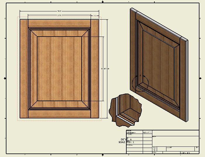
Click here for higher quality, full size image
From the original questioner:
That is exactly it! I don't have Inventor, so I would need to know how to do it in regular Autocad 3-D.
From contributor D:
Draw it the same as you would build it. Make a stock profile and extrude for stile and rail. Cut tenons on the rail to fit stile. Try a tapered extrusion for the centre panel. Assemble. Some commands to practice with are extrude, slice, join, subtract and align. If you need to stretch doors for a lot of sizes, you should check into a utility like Smartlister.
From contributor E:
I can absolutely recommend Smartlister; it is a phenomenal product. It integrates with Autocad and allows you to create cutlists and many other procedures much more easily.
From contributor E:
Forget the offset command. Use the box command in 3D mode to create your stile. Do the same for the rail. Connect the rail to the stile. Use mirror3d command to finish the frame (this'll take figuring out: f1 key!). Draw a line around two sides of inside of the frame, and move it away from the frame. Make a region out of your 2D molding profile. Connect the end of the line to the appropriate osnap on the molding profile. Use the extrude command, choose path, and the molding will follow the path. You can actually do this around a full rectangle, if you want. Slice your molding using the 3 point option. Use mirror to create the other two sides of the molding. Use slice again to create your cuts. Move it all back to your frame. Then work on your panel. Commands: Mirror3d, Slice, UCS, Extrude, Move, Line, etc.