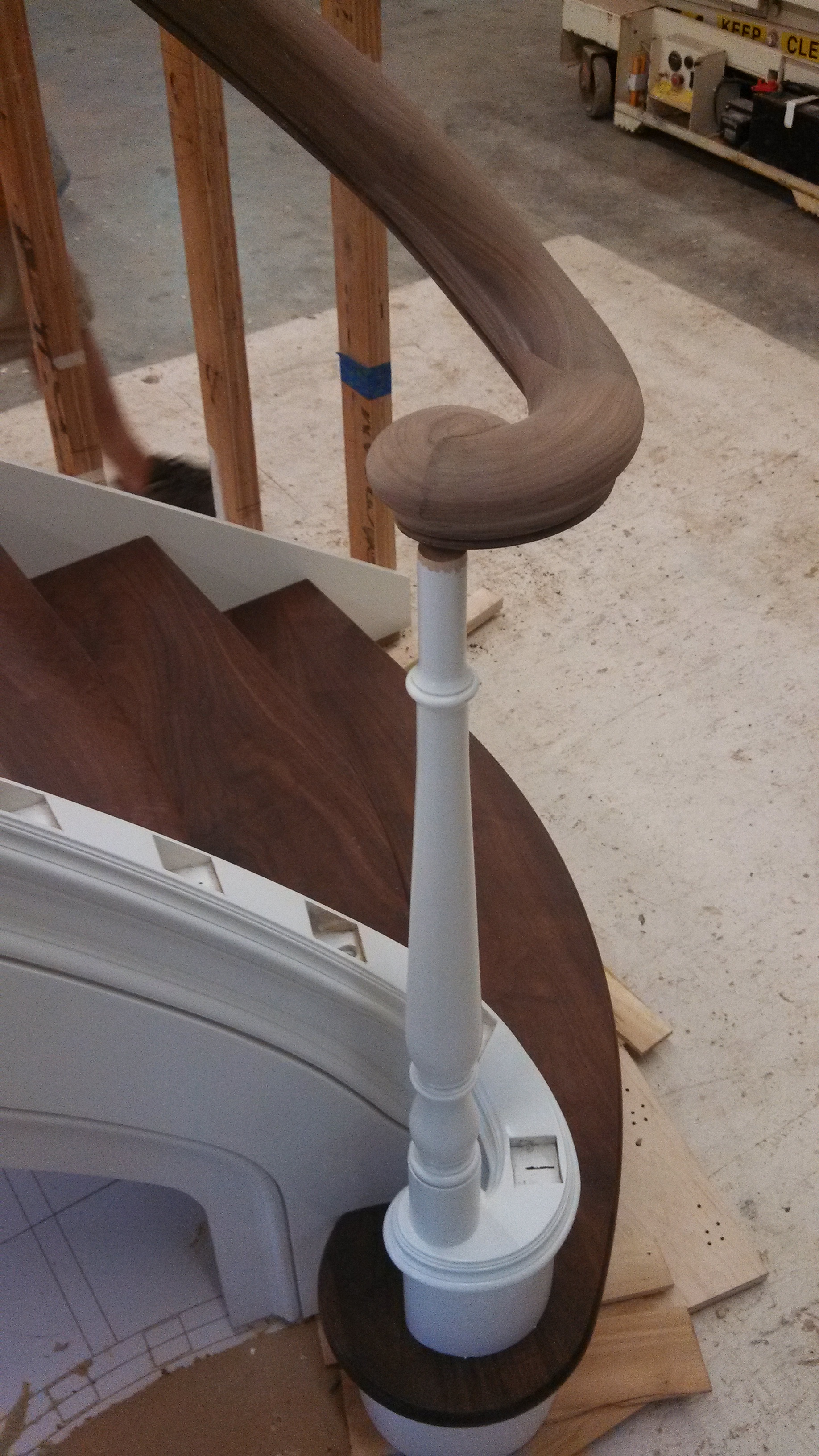
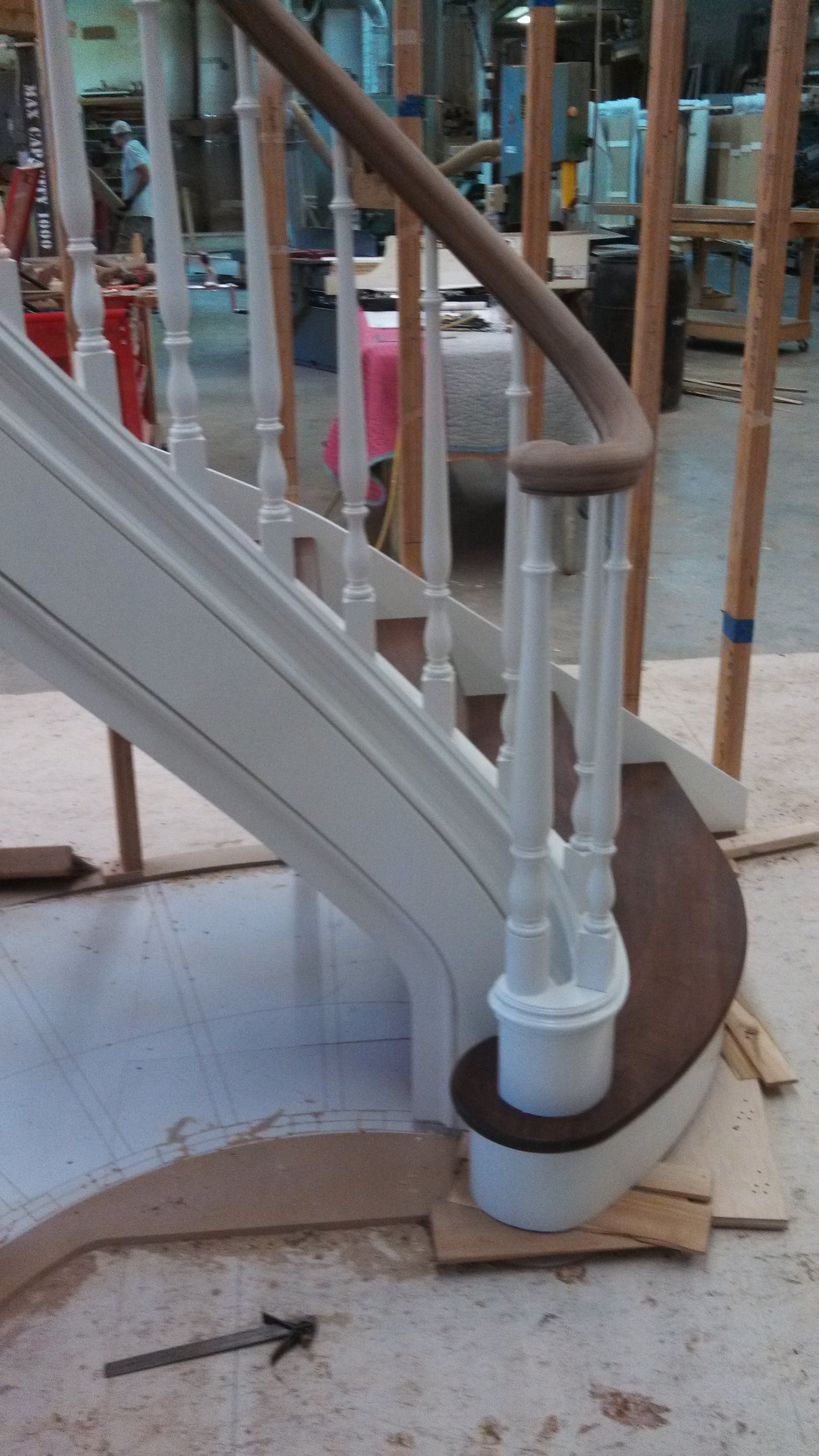
The job my original post was instigated by has concluded. It came out great, hand carved turnout, wreaths and all. Everybody is happy. I learned lots.
Figured i'd post a couple pictures and descriptions of what i learned specifically related to my original questions about fabricating standard handrail fittings. The up/over easings turned out to be super simple. i could not figure out how to make a 'swing jig' (and still have not seen such a thing) but made a pattern guide based on a 10" outside radius for both.
To make the fittings here were my steps
1. glued up big enough pieces with grain orientations i liked
2. milled flat
3. cut out the approximate curves on the bandsaw
4. hot glued the pattern to the blanks and pattern routed the curves to exact curves with a 10" outside radius and the needed inside radius.
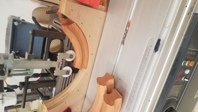
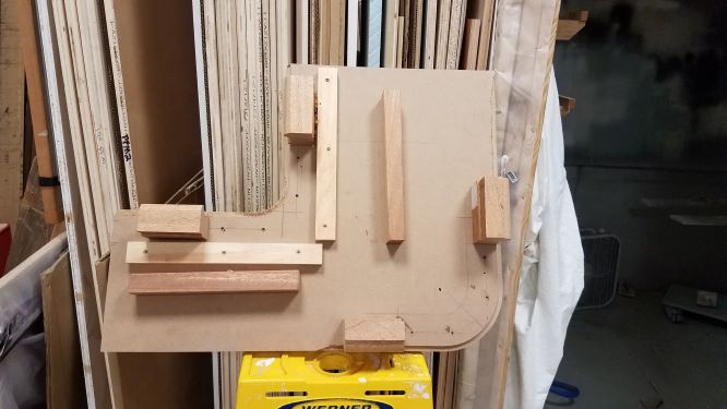
5. used the jig setup in the pictures using a vertically oriented guide pattern to mill the parts in very light passes.
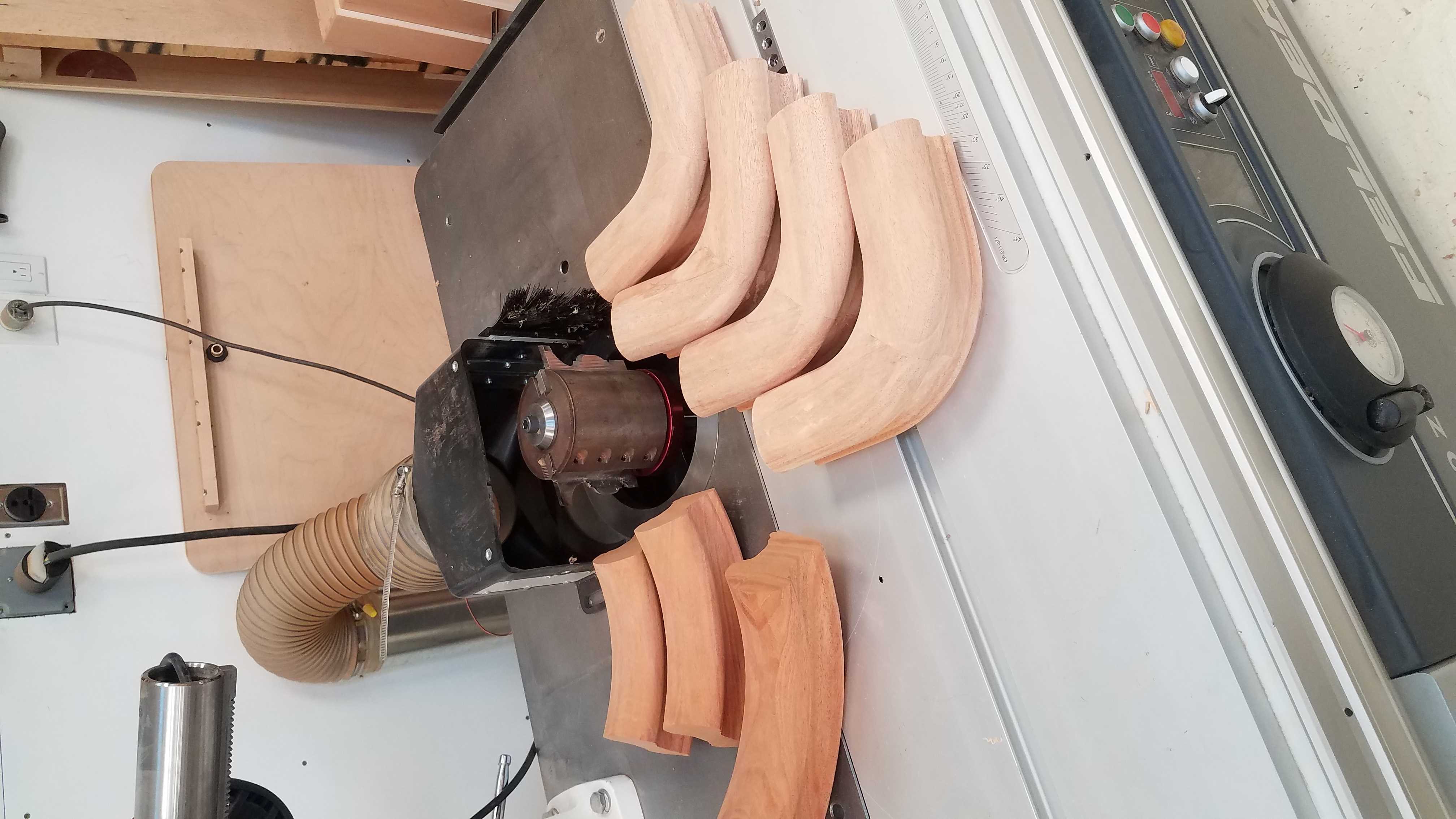
This worked great after i worked the kinks out. mostly i realized you need a MUCH longer piece of the circle than will eventually be installed so that it rides lots of the shaper fence on both the infeed and outfeed side. I now have a terrifyingly mangled short up easing that sits right on the shaper to remind me to be less stupid. It was partially sucked in and thrown, I was fine. Lesson learned. Unfortunately making the easings much longer than needed does not result in the ability to use a single easing for multiple fittings despite the part being plenty long for 3 or more. This was due to the grain orientation becoming increasingly out of line the further from the center of the easing you move. The picture shows only the trimmed down chunks I brought to the site.
I also realized in the future I will use cutters that have most of the ‘top’ of the handrail profile on a separate cutter. To minimize the overall projection of the cutters from center. The length of the maximal projection of the cutter significantly alters the profile as the part is ‘swung’ through the jig. Imagine how a cutter cuts a flat piece, at the maximum cutter projection. The cutter basically cuts nothing as it enters and exits the wood. Now imagine the part going through the curve in the jig shown. The cutter cuts starting at the fence – not just the maximal cutter projection - at both the front and back of the part at different points in the vertical profile of the handrail. Its hard to explain this, but readily apparent when you see the setup. I knew this was coming, but it was more exaggerated than I expected. I made it work, but could save lots of carving sanding during install by having essentially just the side of the handrail profile on one cutter, and the top on another next time. I would ‘swing the parts, then make another jig to hold the curved easings flat on the table and make the top profile.
Next is level 90s. I thought these would be easy, but they turned out more challenging. My original intent was to make them out of solid thick stock, with the grain running 45 degrees to the part. I would then use a custom router bit to make the profile (my shaper will run router bits). The reason for using a router bit was to reduce the cutter maximum radius, allowing me to reduce the inner radius of the fitting. I quickly realized the grain orientation made this too prone to failure. I also ruined a very pricey beautiful router bit on my first part. So I made the ‘standard’ glued up version with the shaper head. The large diameter of the shaper head means the minimum inside radius of the parts is about 2” which works some of the time, but not always. Plus I would like to be able to consistently fabricate a tighter inside radius. If anyone knows of a way or tooling to achieve this let me know (I dont have space for a pin router) Vexor led me to ‘lock nut cutters’ which seem like they could work but are an outdated technology and would potentially mean two sets of cutters for one rail profile. Ideally I would like to find a 5/16 corrugated head that is small diameter, or something similar. The custom router bit option is pricey and cannot be flipped in the shaper.
Level 90 Process
1. Glue up stock as needed
2. Cut out and tenon together 45deg sections about 10” long on each ‘leg’.
3. Pattern rout on the shaper to exact handrail level 90 plan view shape
4. Screw blanks to jig. The screw holes are located where bungs for zip bolts go.
5. Use shown jig to shape profiles in successive bottom mounted bearing guided passes. I just kept stepping down the bearing size about .125” at a time. The jig holds an outside and inside piece simultaneously, so once I got going I could do two at once. Cutting that inside radius is still a bit scary, but the giant jig helps stay far away and have control.
As I said, it all came out great in the end. The hand carved parts were definitely the fun part – and way more challenging. I hope to get that type of work more, but just being able to offer standard rail and fittings in non-fingerjointed stock, and unlimited species/profile options will be good. From here I can make any ‘standard’ fitting I can think of.
There were a few people who helped me get this far, some on here and some I call with all my quirky woodwork questions, so thanks! I heard tell of a couple old books with pictures showing stair part manufacturing that they found insigful, but no one recalled the titles. So if anyone knows pleas pass that along. Of course suggestions for improvement are greatly appreciated!

