@david wishengrad
Vcarve Pro and Cut 2d Pro have the functionality to optimize for yield and nest individual dxf parts. They both do True Shape nesting in that parts can rotate to achieve better yield and, parts can nest within parts. Think small part being nested in the donut hole.
You can also import dxfs that represent optimized sheets of parts.
My design program generates optimized dxf patterns that are not only optimized for yield but, also optimized to help with small part handling and part cutting order. I want parts cut in a cabinet number order to prevent unnecessary sorting and part handling.
You asked about:
are parts always connected to the sheet until the end of the cut?
You can define trim cuts and sheet borders to keep parts connected to the sheet for as long as possible during the cutting process to prevent small parts from falling off prematurely.
You asked:
Is the vertice order of the geometry used or ignored in the tool path?
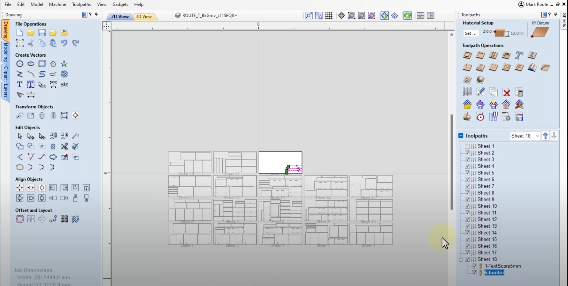
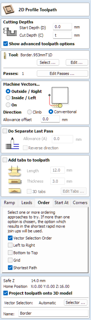
Both Vcarve and Cut2d offer complete sets of configuration choices related to the order of cuts at the tool level. They also provide an excellent animated toolpath previewer that helps you dial in details like where the cut will enter and exit on each part, the cutting order of small parts vs non-small parts and the order of machining per tool. I�ve never seen a more complete set of controls and Vectric has done a great job of presenting these configuration values in the programs user interface. See picture below.
You asked:
Can the strategies be user defined to any layer name?
Layer names are used to make the match to specific tools that will machine the geometry on those layers. For example, a part outline on a layer named "border" will be cut with the tool designated for border cuts on nested parts.
Unlike more expensive CAD/CAM software, Vectric programs do not utilize 3D model information to generate toolpath depths. Instead, cutting depths are set individually for each tool at the toolpath configuration or strategy level.
While 3D model-based toolpaths offer benefits, they also introduce complexity that 2D-based toolpaths can avoid. Vectric's toolpath configuration works well with sheet size and thickness specifications, providing an effective alternative to 3D methods.
While I initially used 3D DXF-based toolpaths with software like CabinetWare and have used KCD for the past 23 years, I have found that Vectric's 2D-based approach provides an effective alternative with less complexity - though it may sacrifice capabilities of 3D toolpaths some folks need.
Vectric's 2D toolpaths provide a good balance of:
- Simplified workflow that does not require 3D modeling knowledge
- Fine-grained toolpath control at the tool \ individual part level
- Helps to simplify the difficult setup task required by design programs when doing 3d dxfs
Working with 2D data in design software simplifies that setup process. Z-values \ depths do not matter - only the layer names assigned to each tool or machining detail.
Vectric software allows you to precisely define machining depths for each tool. For example, you can set 5 mm adjustable shelf holes to drill 14 mm deep.
By specifying the sheet thickness separately (e.g. 19 mm), Vectric will generate G-code to drill 14 mm deep holes in that material. The same toolpath configuration and 14 mm depth can be used for different sheet thicknesses. You do not need to modify toolpaths for different material thicknesses required for standard cabinetmaking on varying material thicknesses.
You asked about resources for learning Vectric software.
YouTube channel LearnYourCNC provides excellent tutorials for Vectric programs.This channel content helped me understand several important concepts I wish I had learned sooner.
One of his videos helped me learn how to define "relative" toolpath depths that adjust based on sheet thickness. Instead of specifying an absolute depth like "14 mm", you can enter a formula like:
"T-8"
Where "T" represents the sheet thickness. So for a 19 mm sheet, it would cut T (19) - 8 = 11 mm deep. For an 18 mm sheet, it would cut T (18) - 8 = 10 mm deep. This ensures a consistent remaining tenon thickness of 8 mm, regardless of the sheet thickness.
Relative depths are useful for operations like tenon relief cuts that start from the panel face. Sheet thickness in Vectric determines the z-axis origin, so relative depths allow the toolpath to adjust accordingly.
Vectric software excels for standard cabinetmaking operations that don't require varying z-axis depths for different parts within a single batch. If you need automated gcode generation for complex parts with changing z-depths, Vectric may not meet your needs.
While Vectric programs use a 2D-based toolpath strategy, you can still import 3D DXF files. During toolpath configuration\creation, you can select a machining detail and tell the program to read the Z-value from the 3D content and this will set the toolpath value to this value.
However, Vectric software will not generate toolpaths based on unique Z-values for individual parts in the 3D model. The toolpaths are still 2D-based, with a single Z-value specified for each tool.
Vectric does not market their software as nested optimization programs. However, they do offer the ability to import multiple loose DXF files and optimize those parts for material yield. This includes properly placing the parts for nested cutting.
Vectric programs include "Gadgets" that automate common tasks. The built-in Batch DXF Import Gadget can import a folder of loose DXFs or optimized/nested DXFs organized by sheet size.
After the batch import of loose DXFs, you do a selection set of individual parts and apply the optimization and nesting process. It works similarly for dxfs already optimized and nested on dxf sheet patterns. In this case you don�t do the nesting process.
At this point with either loose dxfs or sheets of optimized dxfs you apply a tool path template to generate the data that will be written out as g-code.
I wanted more automation than Vectric's built-in gadgets provided so I commissioned a custom gadget to automate determining sheet size, material thickness, and sheet orientation based on a specific router.
Some machines I create code for have an 8' width and 4' height, while others are 4' wide and 8' tall. The gadget controls the import and placement order of pattern DXFs to match the order my design software generates them. Without this gadget, the import order did not match the creation order.
This gadget is something I spent time with a developer and dollars to pay him for his work. I would not be able to use Vectric programs without this gadget.
You can see in the screen grab below just how detailed Vectric programs are when it comes to machining.