I thought I'd share this interesting result I got today carving Versatex PVC with a 60� V-bit. The attached image shows a cut chart created with an Amana RC-1108 single carbide insert 60� V-bit.
I've been carving a specific sign repeatedly in my retirement shop. It's made on 3/4" PVC by applying a face mask with Oramask 813, then carving with the Amana bit, then the letters are painted, the mask removed and the face cleaned up by random orbit sanding from 220 to 600.
For the past 4 or 5 years I've been making this on Palight brand PVC. I've gotten decent carving results with the about 1/8" wide V-carved letters needing a little more attention than just a 90 psi air gun to clear out the chips left behind. The signs were 3D carved with the Amana bit a 15,000 rpm and 150 ipm feed rate.
Recently though I acquired some Versatex and to my mild dismay I found I was getting heavy chip residue in the cuts after carving. It comes out with an awl pushed along the cut but obviously this is less than ideal. So the Versatex core is different enough from the Palight to give different carving results.
Meanwhile I recently bought myself a light duty laser engraver. Even in retirement I have a few customers (not related to my old curved moulding business) and produce some things to wholesale to them plus I sell my signs. The laser engraver seemed like a nice addition to this little business.
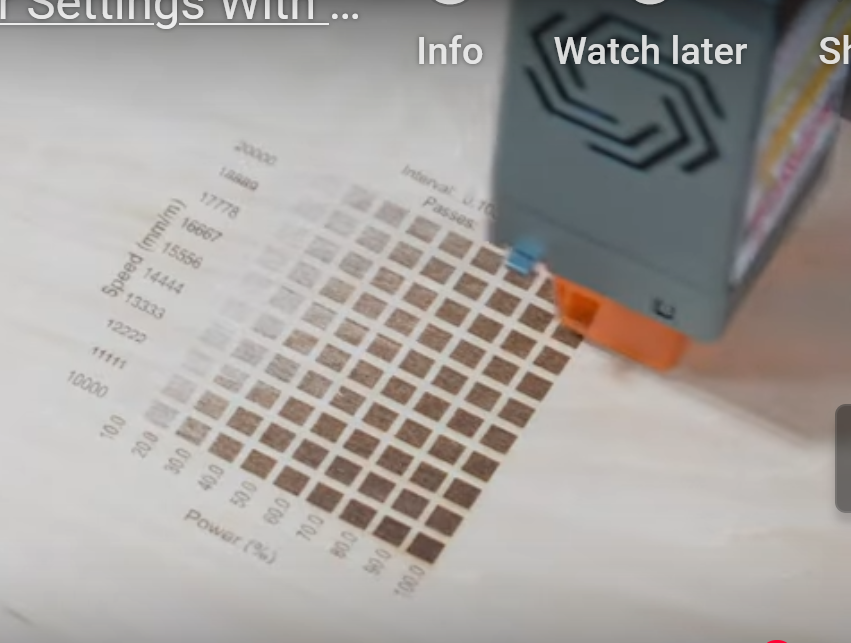
I bring the laser into this discussion because the Lightburn software that controls it has a really nice feature I'd never seen before. When you cut a new material for the first time, just like on a CNC router, you have to determine the optimal feed rate and power levels (lasers vary the power output as vs. the the spindle rpm's). You input the minimum and maximum power you want displayed on the chart and the minimum and maximum feed rate. Then the laser produces a series of small squares that have been etched using the increasing travel speed across the bottom of the chart and the increasing power level going up the side of the chart. If you had 5 feed rates, and 5 power levels you would get 25 small squares showing the results of the intersections of the various speeds and power levels.
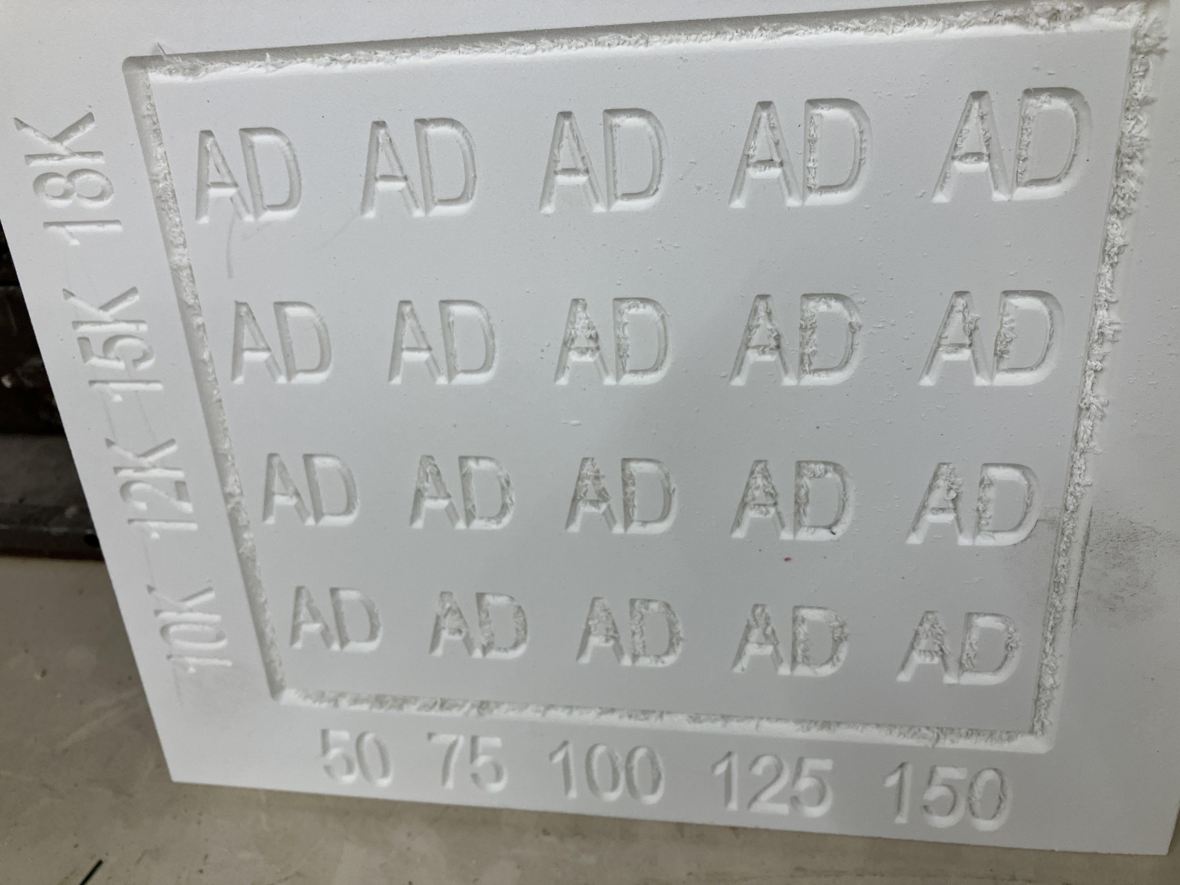
Well, today it occurred to me to create a similar V-groove chart in PVC to see what feed rate/rpm combination gave me the best results. I used two letters that tend to accumulate a lot of heat welded chips to the carved line: A and D. Low and behold, I didn't get the results I expected.
I would have thought a higher rpm at a lower feed rate would kept the V-bit in contact with a given point of the surface for longer, thus resulting in more heat and more heat bonding of chips to the cut surface. That though did not turn out to the the case. As you can see in the photo it was the slowest feed rate at the highest RPM that resulted in the cleanest result. Just the opposite of what I expected.
There are special bits made for cutting plastics like PVC and acrylic. There's one design I'd never heard of until recently....O-flute bits. They have a single flute with a large gullet that quickly slopes away from the cut edge. This is to give chips a quick and easy path away from the cut. I have a couple of those in 1/4" diameter (a 30� and a 60� version) but that isn't large enough to cut my sign letters without going into a stepped slope cut which is less than ideal for a number of reasons. So I called Amana tech today and asked what they had for this situation. They had no large O-flutes but they do have one particular bit designed for cutting a 60� V-groove in plastics. It is thieir 45731. Very strange looking single flute bit at about $35.00. I'll probably get one to try.
I thought this material chart was an interesting concept to apply to cutting new and different materials. It doesn't have to be a V-groove chart either. You could make a bunch of short slotted cuts with a straight bit for example to see which feed/speed combo works best on a product you've never cut before.
BH Davis